First of all, I just want to confirm what AC adapter these things are supposed to use. From what I've heard, it uses the standard PSone adapter. I don't even have one of those, but I did have a 7.5v 2100ma adapter for an old USB hub. I found a connector that would fit into the PSone and switched it with the one on the AC adapter, and was good to go. That's how I found that the PSone worked, and the LCD apparently didn't. Hopefully I'm not feeding it too many amps, though.
Next, I found that the pole in the power jack on the screen was broken. It took a bit of poking around to figure out why I wasn't getting any power at all, until I finally noticed the solder completely separated from the power/input board. This made sense, because the PSone wouldn't power on at all when the AC adapter was plugged into the screen instead of directly onto the console. After opening it, I found that the power should pass directly through to the console, but wasn't happening due to the trace being split in half from the break.
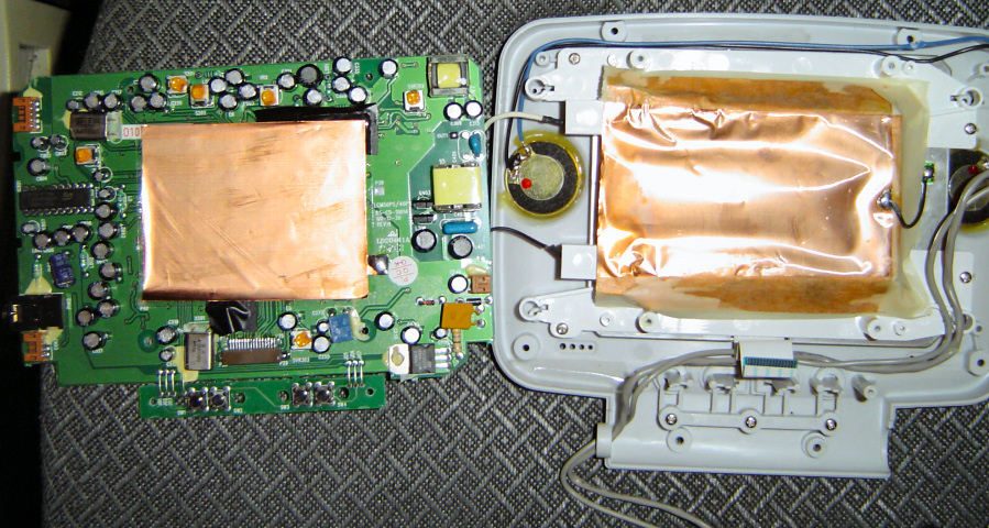
So, I cut the power connector cable that goes to the screen's PCB and wired the AC adapter straight to that. Even that didn't turn out as easy as I thought, because the wires are apparently the wrong color. The black wire leads into the power circuitry, while the red wire apparently goes right to the ground connections.
Once wired the right way, I did some basic testing with the multimeter. Power is certainly being fed into the 7805 regulator, and 5v is definitely coming out. From there I really have no idea what's wrong.
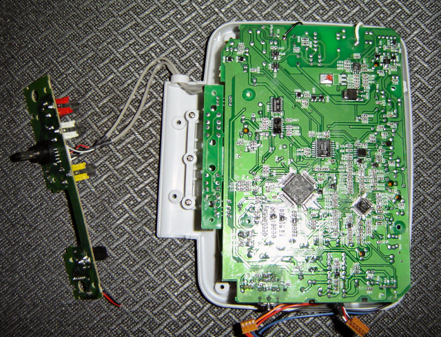
Does anyone know of any little fuses or anything that might be hidden on there and causing the problem? I perused the board but don't think I saw any from first glance. I also tested the power button itself to make sure it was still working, then the connectivity of the connection up to where it leads (a pin on the square chip that's rotated 45 degrees).
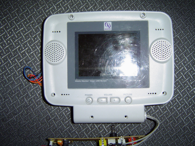
Even if the board is fried, the LCD could be promising. It's a Toshiba TFD40W11-B. Unfortunately I can't find a datasheet anywhere. But I did find this:
1[in] logic power (5V)
2[in] horiz sync input
3[in] vert sync input
4[out] signal voltage / phase inversion control out
5[in] ground Vss (0V)
6[in] R video
7[in] G video
8[in] B video
9[in] common voltage input
10[in] Vbb (13V)
11[in] Vgg (25V)
12[out] common voltage / phase inversion control output
13[in] Vss (0V)
14[in] NTSC/PAL selection
15 NC
16 NC
Apparently it's capable of directly accepting RGB and sync signals. But I have to admit that wiring one up to something without something to go by is a bit out of my league. Mostly for the pins like Vbb, Vgg, etc. I'm assuming that backlight is CCFL, which would also take a bit of effort to get going, since I think they need an inverter to get 100v or something.
Anyway, any help anyone can provide would be much appreciated. If nothing else, maybe somebody will find some use from the pinout and/or pictures. Thanks in advance!