Here,
megaupload.com2010.09.13.zip
File contains
- an Eagle 5 schematic and board art with the afore mentioned circuit plus a power connector and breakout (incase you wanted to do something more than program the chip).
- the same in PDF format
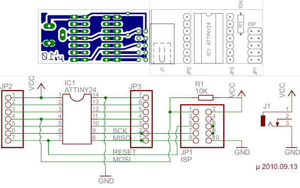
The board is single sided, with the foil on the bottom and the components on top.
(from left to right)
J1 is the power connector, with the center pin (top most) positive.
JP2 and JP3 are breakouts linked to each pin of the chip.
IC1 is the ATTINY24
R1 is a 10K resistor pulling MOSI/IC1.Pin4 up (to VCC).
JP1 is the ISP (in circuit programmer) orientated with pin 1 on top.
On the bottom of the board
µ`10 has been printed to verify that the pcb is not mirrored backwards/upside down (It happens to my colleagues far more often than they'd like to admit, and we all have more than one degree!)
A ground pane has also been added to minimize the use of etchant while developing.
The PDF has been deliberately made smaller than a sheet of paper so that 'automatic-scaling' does not screw a toner/film transfer to PCB. Make certain that there is no additional scaling. The bottom layer will print pre-mirrored for toner/film transfer.
Sorry about the choice of file host; it's free but the client is really bad on memory leaks, this little 47K zip balooned to 314MB for some inexplicable reason.
Also, tell me if this design is too compact to for you, I am trying to break my bad habits of intersecting components (ie: resistor under the chip between the rows of the socket), or putting components too close for most people to populate the board (ie: IC's less than 0.1" apart).
EDIT: picture inserted