what is the ma draw from the gamecube? the link is deadGamelver wrote:As is turns out, the Gamecube can in fact output an RGB signal, perfect for our favorite portablizing screen(the psone screen)!!!! Also, you can get VGA from the GC if you want
.
First of all, you're gonna need a component cable for the GC. Here's a place where you can get one
Once you've got your component cable, then open it up and start modding!!!!...according to these guides, of course...
SNES/N64/GC pinout (please note that the RGB doesn't work on the GC, either)
S/PDIF mod
RGB/VGA mod
more on RGB mod (fourth post down)
how to get c-sync out of compositethanks usbcd36 for originally posting theseusbcd36 wrote:Here is a connection diagram:
Connect wires along all the black lines, do not connect any intersections. Connect wires along the white lines as well, and tie all grounds together somewhere.
oh yeah, and when I have time, I'll probably add some video mods for the PS2/XBOX, too...
also, I'll add all I know about the GC
Edit: I'm gonna put up the thread with all my "useful" GCp posts...enjoy
GCp info
GC mA measurements!
NOTE: the gamecube does NOT require 12v on the 12v line, according to shockslayer it will work with as little as 5v!
Gamecube video mods+GC info
Moderator:Moderators
-
footinmouth
- Posts:126
- Joined:Sun Mar 23, 2008 9:42 am
- Location:CANADA

i hate how electronic part suppliers give you an option on their website to filter your searches so that you can find a certain part and no results come up!
-
footinmouth
- Posts:126
- Joined:Sun Mar 23, 2008 9:42 am
- Location:CANADA
im going to do some experienting to see if the 5 volt mod is possible on rev 2 gc'sShockSlayer wrote:Just use a 12v battery and a composite screen and you will be fine!footinmouth wrote:Is it possible to do on the second revision gamecube models? cuz i still want to use this one even if I can't do an rgb mod on it, the reason is because this one has a built in power regulator on the motherboard
Also; something else to note:
Ok, I have confired that all platinum gamecubes without the Digital av port lack a powerboard. I checked all of them at my local gamestop, and it is even possible to see if its not open! Just look in the back vents and there will be nothing where the powerboard should be. All the platinums with the digital av out have the powerboard.
SS
i hate how electronic part suppliers give you an option on their website to filter your searches so that you can find a certain part and no results come up!
-
ShockSlayer

- Niblet 64
- Posts:5059
- Joined:Thu Jun 29, 2006 12:47 pm
- Location:In my inbox.
I concur. If I'm not mistaken, the DD would fry if that happened.Kyo wrote:make sure to remove the 12V input then, because otherwise you'd be upping the 5V line and not vice versa
SS
http://twitter.com/ShockSlayer" onclick="window.open(this.href);return false;
This is a bit contradicting. From what I understand, the diagrams would have to be like this:All right here's a pinout of the power regulator voltages:
first of all here's how the power regulator board looks:
all you really have to worry about are pins 12-22. pin 13 is 3.4v, pins 16-18 are 1.9v, pin 21 is 12v, and pin 22 is 5v. also you have to make sure you have ground.
here's the pins on the GC ( that box with the lines is the heatsink....I suck at paint):
pins 2 and 13 need 3.4v, pins 6,7,16,17,18,19 need 1.9v, pin 10 needs 12v, and pins 11 and 22 need 5v. just make sure that the pins that I've grouped together, like 6, 7, 16, 17, 18, 19 are connected together. they should be, though.
and that's how you only need 5 wires to attach the gc power regulator board to the GC board!!!!!!!!!!!!! that "bit of bad news" was that a gc regulator had fried and so I ordered another one....
* oh yeah if you turn on your GC and you don't get any sound, try getting the 12v not from the pin on the GC power regulator, but directly from the actual GC ac adapter. I also tried that from the 14.8v li-poly battery pack and it worked fine.


However, that is contradicting. I'm trying to write an article about the 12V/5V thing on my site (Well, copying SS's article and adding some pictures, to be precise). I decided to take actual pictures, because a picture says more than thousand diagrams (:P).
Could somebody tell me which one is right, and how I would have to correct it?
thanks
-
ShockSlayer
- Niblet 64
- Posts:5059
- Joined:Thu Jun 29, 2006 12:47 pm
- Location:In my inbox.
Umm, okay. I'll field this one.
From my truth: both diagrams are wrong.
Kyo, all yours does is switch the rows on both sides of gamelver's(or whoever's), and thus changes absolutely nothing.
Flip a coin and pick the power board or the game cube and switch only one of the rows.
SS
From my truth: both diagrams are wrong.
Kyo, all yours does is switch the rows on both sides of gamelver's(or whoever's), and thus changes absolutely nothing.
Flip a coin and pick the power board or the game cube and switch only one of the rows.
SS
http://twitter.com/ShockSlayer" onclick="window.open(this.href);return false;

Actually, one is the top the other one is the bottom, so they should have the same numbering, as in reality, the power board is under the other one, which means that they should have the same numbering at the top and bottom, but they don't. That's my problem.ShockSlayer wrote:Umm, okay. I'll field this one.
From my truth: both diagrams are wrong.
Kyo, all yours does is switch the rows on both sides of gamelver's(or whoever's), and thus changes absolutely nothing.
Flip a coin and pick the power board or the game cube and switch only one of the rows.
SS
DaStan, thanks. So which one of these used to be 12V? 19, right?
-
ShockSlayer
- Niblet 64
- Posts:5059
- Joined:Thu Jun 29, 2006 12:47 pm
- Location:In my inbox.
Well, it doesn't really matter which row is which. The top row of pins is the exact same as the bottom.
SS
SS
http://twitter.com/ShockSlayer" onclick="window.open(this.href);return false;
-
ShockSlayer
- Niblet 64
- Posts:5059
- Joined:Thu Jun 29, 2006 12:47 pm
- Location:In my inbox.
Here is a diagram made by Mario(the benheck user, named after the plumber  ) that shows you how to make a low battery LED indicator. You need a zener diode with a voltage rating equal to the voltage your battery drops to a little bit before it dies, a 2.7v LED or similar voltage, a common 2n3904 transistor, and a 1k resistor.
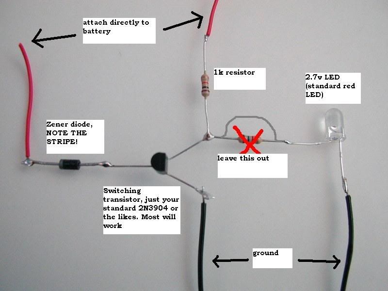
You might need to adjust your zener diodes with a resistor, to get the led to come on before it dies.
Disscusion thread is here.
Tutorial thread is here.
Does a mod want to split the posts out of that topic?
SS
You might need to adjust your zener diodes with a resistor, to get the led to come on before it dies.
Disscusion thread is here.
Tutorial thread is here.
Does a mod want to split the posts out of that topic?
SS
Last edited by ShockSlayer on Sat Jan 10, 2009 11:23 pm, edited 1 time in total.
http://twitter.com/ShockSlayer" onclick="window.open(this.href);return false;
-
palmertech

- Senior Member
- Posts:3225
- Joined:Sat Feb 02, 2008 1:40 am
- Location:California, land of the homeless and hippies
- Contact:
