* Login 
* FAQ    * Search

All times are UTC - 6 hours


Post new topic Reply to topic  [ 35 posts ]  Go to page 1, 2, 3  Next
Author Message
 Post subject: How to Add a Low-Battery Light to Your Portable
PostPosted: Sat Jan 10, 2009 10:37 pm 
Offline
User avatar

Joined: Mon Mar 05, 2007 7:20 pm
Posts: 1382
Location: Sunny California
Here is a better guide:
http://forums.modretro.com/viewtopic.ph ... 4776#p4776

Maybe you have seen the discussion in ShockSlayer's GCP thread. We have figured out how to make an easy low voltage indicator for your portable.

If you haven't seen it, where have you been for the past 2 days!? :lol:

Here is a guide telling you how to add one to your portable. Note that the best time to make this is when you have your portable's guts done, so you can accurately measure the low-voltage point of your batteries.

Here is a list of parts you need:
1W 1k resistor
2.7v LED (Regular red LED)
A couple zener diodes (more on that later)
2N3904 transistor or equivalent (like 2N2222 or 2N4401)
Optional:
2.7v LED (Regular green LED)
50-100ohm resistor

To start, you should have most of your portable done, i.e. the functioning guts of it, all running from the batteries. Run your portable until it dies, and measure the voltage that the batteries are at.

For example, say that you have 7.4v li-ion batteries that are really about 8.3v when charged. If you were making, say, an N64 portable, everything might shut off when that batteries got to 7.0v. Record that voltage and remember it. Add about 0.2v to it to get the voltage you would want the low battery light to come on.

So what we have now is the voltage that everything dies at, 7.0v. Add 0.2v to it, so we have 7.2v. That is the voltage we want the LED to come on at. Remember, these are just an example. If you have 12v batteries for something like a Gamecube portable, your batteries might die at 10v. You would then add 0.2v and get 10.2v.

Now, you need to buy zener diodes. If you want to know how these work, look at the second-to-last paragraph. If not, you aren't missing anything important.
You can find zener diodes on eBay. There are 18 standard voltages you can use: 2.0v, 2.2v, 2.4v, 2.7v, 3.0v, 3.3v, 3.6v, 3.9v, 4.3v, 4.7v, 5.1v, 5.6v, 6.2v, 6.8v, 7.5v, 8.2v, 8.7v, and 9.1v. You will need to find which ones to add together to get the voltage you want. For my example, we could add a 2.2v and a 5.1v diode to get 7.3v, or a 4.3v and a 3.0v - quite close to the voltage we want. For the 10.2v example, you could use two 5.1v diodes. You can also use a variable resistor to fine-tune this voltage, more on that later.
To find the diodes, search "zener diodes X" where X is the voltage you want, like 2.2v or 5.1v. Here is an excellent store that sells all those voltages of diodes.

The other electronics are easy to get. If you have a RadioShack near you, good. You'll be able to pick up everything you need for pretty cheap. Get a 1W 1k resistor. It MUST be at least 1 watt because if it isn't, it will heat up and possibly catch fire - certainly something you would not want inside your portable. What this resistor does is act as a load for the batteries, so that under normal conditions, the battery is not just shorted to ground. (See the last paragraph)
You need a standard switching transistor, most will work fine. You may have some lying around. You need a 2N3904, 2N2222, 2N4401, or any NPN transistor. You might find one in some broken electronics.
You also need an LED, obviously. Get a regular 'ol red LED; these take about 2.7v.
The optional pieces are if you want a two-LED indicator, like on the Gameboy SP or Nintendo DS. These are green when all is good, then turn red when the battery is low. You could either use two separate LEDs or a bi-color LED, both you can get at RadioShack, but the bicolor ones are almost $5 apiece.

Anyway, for the optional stuff you'll need a 50-100ohm resistor and another LED.

Now about actually building the circuit. Here is the diagram for the one-LED one:
Image

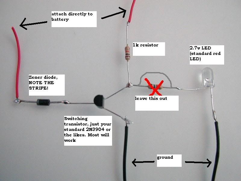
It is a very simple circuit. Note the direction of the diode; the stripe is critical. If you get this wrong, the circuit will not work. If you have two or more diodes, put them in series.

EDIT: I tried this circuit and could not get it to work, the green LED draws too much power compared to the red one and it does not function. Please disregard this diagram until I figure out a better way for this.
Here is how you would have a 2-LED indicator:
Image

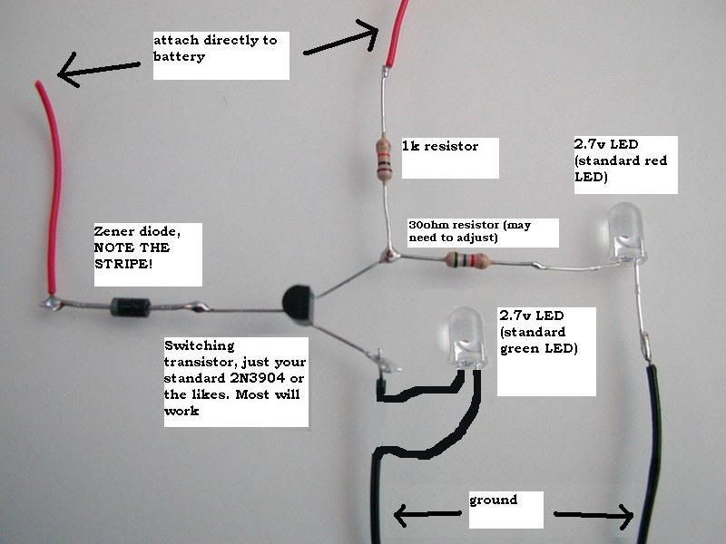
The resistor right before the LED does not have the proper color coding, it is just a random resistor, so don't go by it. A 100ohm resistor would have a color code of Brown-Black-Brown-Gold.

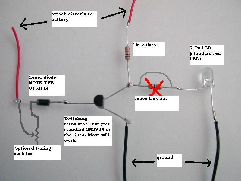
If you are having problems with getting the indicator to go off at the right time, this will fix it. This is only if it goes off too late for your liking.
This modification is easy. Just add a 10k variable resistor between the diode and the battery. Adjust as needed. The higher you set it, the sooner the indicator will go off.
Image

Thank you for looking. Hope you find this information useful! :D

How Zener Diodes Work:
Zener diodes are just like normal diodes except with one difference. Their breakdown voltages. The breakdown voltage of a diode is the voltage it takes to pass a current backwards through a diode. The problem with normal diodes is that this voltage is very high, and when you reach it, it damages the diode. Zener diodes are specially made to have low breakdown voltages, like 5.1v or 3.3v, and they are not harmed when you reach it. So say you have a 5.1v zener diode. To pass a current backwards through it, you would need at least 5.2v.

How This Circuit Works:
This is basically a zener diode combined with a NOT circuit. For the example, we will say we are using 7.5v li-ion batteries with the zener voltage at 7.3v. So when the battery is in the "good" state (more than 7.3v), current is getting past the diodes and to the transistor. Electricity always takes the easiest route, so it goes straight to ground. When the batteries reach the critical stage (less than 7.3v) then current no longer passes through the diodes. The transistor is disables, so the only route for the electricity to take is through the LED.

Final note: The amp draw of the one-LED circuit is 40mA when the battery is good, and 20mA when it is dying.

_________________
Image


Last edited by Mario on Sun Oct 04, 2009 8:35 am, edited 3 times in total.

Top
 Profile  
 
 Post subject:
PostPosted: Sat Jan 10, 2009 11:17 pm 
Offline
Niblet 64
User avatar

Joined: Thu Jun 29, 2006 12:47 pm
Posts: 5055
Location: In my inbox.
Very awesome guide!

SS

_________________
http://twitter.com/ShockSlayer


Top
 Profile  
 
 Post subject:
PostPosted: Sat Jan 10, 2009 11:35 pm 
Offline
User avatar

Joined: Tue Nov 20, 2007 7:58 pm
Posts: 1141
Location: Ontario, Canada
Nice. So how exactly did you find this out?

Videos?


Top
 Profile  
 
 Post subject:
PostPosted: Sat Jan 10, 2009 11:44 pm 
Offline
User avatar

Joined: Mon Mar 05, 2007 7:20 pm
Posts: 1382
Location: Sunny California
Aguiluz wrote:
Nice. So how exactly did you find this out?

Videos?


I made the circuit myself, using my extensive knowledge of electronics. :wink:

I may put up a video, but I haven't actually built the functioning circuit yet, maybe ShockSlayer could, he has built one that works.

_________________
Image


Top
 Profile  
 
 Post subject:
PostPosted: Sun Jan 11, 2009 12:19 am 
Offline
Niblet 64
User avatar

Joined: Thu Jun 29, 2006 12:47 pm
Posts: 5055
Location: In my inbox.
Mario wrote:
Aguiluz wrote:
Nice. So how exactly did you find this out?

Videos?


I made the circuit myself, using my extensive knowledge of electronics. :wink:

I may put up a video, but I haven't actually built the functioning circuit yet, maybe ShockSlayer could, he has built one that works.


I kinda show it in my video, so wait and I'll kill my battery and video it in the process for you. :lol: :D

SS

EDIT: Okay, I figured one thing you might want to add your guide: when you mention wiring them(diodes) in series, take a second and define series. Some newbs don't know what that is, I had already built 3 portables before I knew this. :oops:

_________________
http://twitter.com/ShockSlayer


Top
 Profile  
 
 Post subject:
PostPosted: Sun Jan 11, 2009 1:43 am 
Offline
Senior Member
User avatar

Joined: Mon Nov 14, 2005 10:19 pm
Posts: 3047
Location: Ontario, Canada
How much power does it use when the light is off?

_________________
Image

"Linux is only free if your time is worthless"


Top
 Profile  
 
 Post subject:
PostPosted: Sun Jan 11, 2009 2:02 am 
Offline
Niblet 64
User avatar

Joined: Thu Jun 29, 2006 12:47 pm
Posts: 5055
Location: In my inbox.
timmeh87 wrote:
How much power does it use when the light is off?

Mario wrote:
Final note: The amp draw of the one-LED circuit is 40mA when the battery is good(off), and 20mA when it is dying.


Red text added for clarification. As he says its the one led circuit, so off = good, and on = dying. :D

SS

_________________
http://twitter.com/ShockSlayer


Top
 Profile  
 
 Post subject:
PostPosted: Sun Jan 11, 2009 2:19 am 
Offline
Niblet 64
User avatar

Joined: Thu Jun 29, 2006 12:47 pm
Posts: 5055
Location: In my inbox.
http://www.youtube.com/watch?v=o87Wa4ii4Y4

9:37

You can kinda see it in action, as my battery wasnt dead, but if flickers when turning on and off like it should.(it does this in the GBASP)

_________________
http://twitter.com/ShockSlayer


Top
 Profile  
 
 Post subject:
PostPosted: Sun Jan 11, 2009 2:46 am 
Offline
Portablizer Extraordinaire
User avatar

Joined: Fri Apr 20, 2007 12:14 am
Posts: 3984
Location: Hampshire, UK
Please also describe how to know the wattage of a resistor as you mentioned how critical it is to be at least 1 watt.

Another thing - how safe is this mod - ie is the resistor likely to fail at any time, causing a fire?? Can you build in redundancy - eg two 1 watt resistors? Comments? Not keen on the prospect of having a portable melt or house burning down if a resistor fails...

_________________
Image


Top
 Profile E-mail  
 
 Post subject:
PostPosted: Sun Jan 11, 2009 3:26 am 
Offline
Senior Member
User avatar

Joined: Tue Jan 02, 2007 11:59 am
Posts: 2470
Location: Germany
I doubt a resistor would start a fire. The worst case is the thing not working anymore.

Normal resistors are 1/4W. That's probably what you have. You'll have to buy some.

_________________
Free webcomic hosting

Console Modding/Portabilizing info site - contribute today!


Top
 Profile  
 
 Post subject:
PostPosted: Sun Jan 11, 2009 6:00 am 
Offline
Portablizer Extraordinaire
User avatar

Joined: Fri Apr 20, 2007 12:14 am
Posts: 3984
Location: Hampshire, UK
Kyo wrote:
I doubt a resistor would start a fire. The worst case is the thing not working anymore.

Normal resistors are 1/4W. That's probably what you have. You'll have to buy some.


So, if you put 4 x 0.25 watt 1k ohm resistors in parallel would that give 1K ohm resistors at 1 watt? (like amperage works on batteries)?

Edit - bought some 1K 1 watt resistors just now anyway, above question was out of interest.

_________________
Image


Top
 Profile E-mail  
 
 Post subject:
PostPosted: Sun Jan 11, 2009 8:16 am 
Offline
Senior Member
User avatar

Joined: Tue Jan 02, 2007 11:59 am
Posts: 2470
Location: Germany
no that would give you

1/(1/1000 + 1/1000 + 1/1000 + 1/1000) Ohms at 1 Watt

_________________
Free webcomic hosting

Console Modding/Portabilizing info site - contribute today!


Top
 Profile  
 
 Post subject:
PostPosted: Sun Jan 11, 2009 11:56 am 
Offline
User avatar

Joined: Mon Mar 05, 2007 7:20 pm
Posts: 1382
Location: Sunny California
bacteria wrote:
Please also describe how to know the wattage of a resistor as you mentioned how critical it is to be at least 1 watt.

Another thing - how safe is this mod - ie is the resistor likely to fail at any time, causing a fire?? Can you build in redundancy - eg two 1 watt resistors? Comments? Not keen on the prospect of having a portable melt or house burning down if a resistor fails...


You know what the wattage is because the package should tell you, but you know by the thickness of it.

I tried this out with a 1/2 Watt resistor, and it only got slightly warm. A 1w is a huge safety margin. Plus it lowers the amp draw if there is less heat.

I made a correction to my first post - The two-LED circuit does not work. The resistor and red LED is still the easier path for the electricity, and the green one won't come on.

_________________
Image


Top
 Profile  
 
 Post subject:
PostPosted: Sun Jan 11, 2009 12:10 pm 
Offline
Senior Member
User avatar

Joined: Tue Jan 02, 2007 11:59 am
Posts: 2470
Location: Germany
Couldn't that be fixed by changing the resistor values?

_________________
Free webcomic hosting

Console Modding/Portabilizing info site - contribute today!


Top
 Profile  
 
 Post subject:
PostPosted: Sun Jan 11, 2009 12:52 pm 
Offline
Senior Member
User avatar

Joined: Fri Mar 25, 2005 8:25 am
Posts: 6313
Just put a switch in that circuit (make sure both postives or grounds are tried together at the switch). Then you can turn it on, see how the battery is, and turn it off again.
Can't the same thing be done with resistors and a few LEDs? Like have the "full battery" LED with a high ohm resistor, and lower the ohms for the next LEDs. That would for sure require a switch to save power/components' lives.

_________________
Image


Top
 Profile E-mail  
 
Display posts from previous:  Sort by  
Post new topic Reply to topic  [ 35 posts ]  Go to page 1, 2, 3  Next

All times are UTC - 6 hours


Who is online

Users browsing this forum: No registered users and 0 guests


You cannot post new topics in this forum
You cannot reply to topics in this forum
You cannot edit your posts in this forum
You cannot delete your posts in this forum
You cannot post attachments in this forum

Search for:
Jump to:  
Powered by phpBB © 2000, 2002, 2005, 2007 phpBB Group