Bacteria - Ipaq 3600 PDA resurrected, improved! *DONE*
Moderator: Moderators

-
bacteria
- Portablizer Extraordinaire
- Posts: 3984
- Joined: Fri Apr 20, 2007 12:14 am
- Location: Hampshire, UK
- Contact:
Sure, after all these things can fail after a while and it would be nice to have a backup please as it is cheap, after all they are so old you can't get them anymore as people want the later models now: you mentioned before the cheapest shipping was about $10, any idea how long that takes to arrive in the UK roughly? (if it only costs a couple of dollars more for quicker receipt, it might be worth it). Perhaps you could please PM me with a firm price for the shipping and your PayPal e-mail address, so we can do business mate??vskid wrote:So will you still be needing my ipaq? I really don't care either way, its your money.

-
bacteria
- Portablizer Extraordinaire
- Posts: 3984
- Joined: Fri Apr 20, 2007 12:14 am
- Location: Hampshire, UK
- Contact:
Time for an update.
To remove the need for the D-pad, so I don't have issues with the D-pad thickness pressing against the small mobo, I am using tact switches. I had thought about using 12mm tacts, but this would be far too big, so I am using 6mm ones. Putting the 6mm tact switches in the hole I had previously cut out for the D-pad cross fits quite nicely, however of course the middle bit is hollow. I used hot glue to secure the tact switches in place and put a small square of PVC in the middle and hot glued the back, to keep everything firmly in place. It doesn't matter that it looks bad, irrelevant as it will be covered entirely (as mentioned before), it is flat, with only the tact switch button above the level of the case perspex base.
When I was trying to find the fault before with the calibration screens, I de-soldered the connections on the mini mobo, so I need to re-connect them. My soldering iron is nice and hot now, this is my next job. I will then connect all the wires to the tact switches again.
-
bacteria
- Portablizer Extraordinaire
- Posts: 3984
- Joined: Fri Apr 20, 2007 12:14 am
- Location: Hampshire, UK
- Contact:
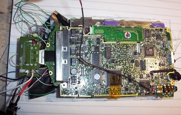
All the connections on the mobo use a common wire - the D-pad, and the 5 switches; so it makes sense to make one wire connect to one of the connectors on each tact switch - saves excess trailing wiring. I stripped the sheath from an electrical wire (single strand one).
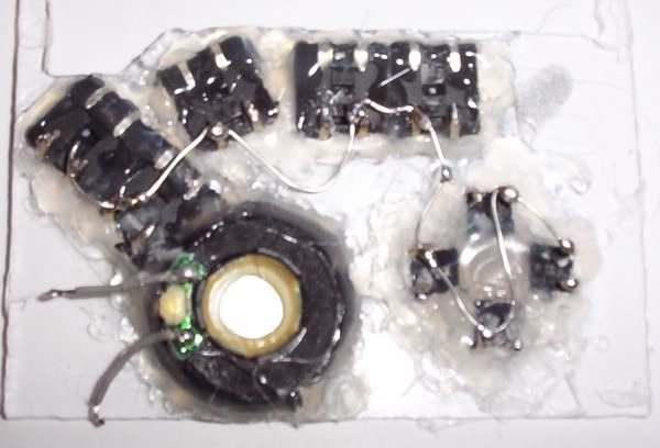
Wiring is complete - I used hot glue to keep the wires in place and stop them coming free.
Next immediate jobs (probably in order, but I may change them about):
* Connect the wires to the tact switches
* Protect all the wire connections with electrical tape
* Secure screen in place
* Test all is still working fine
* Trace out positions of tact switch buttons for my "alternative"
* Rig up the batteries and secure them in place
* Make sides of case, rounded corners; secure two on/off switches in place for the power and USB port
* Design and secure outer reverse spray-painted PVC sheet around top and sides of case, taking care to make the corners look nice
* Make and then secure the buttons in place
* Make reverse of case and have 4 screw holes in place to allow for any future repairs if needed
* Make holder for PDA to locate near my PC
I should, given a fair wind, have this project done by the end of the week.
-
bacteria
- Portablizer Extraordinaire
- Posts: 3984
- Joined: Fri Apr 20, 2007 12:14 am
- Location: Hampshire, UK
- Contact:
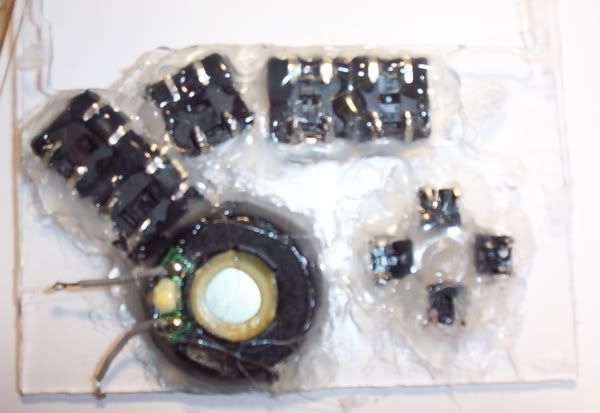
A few more updates before I close for the day:
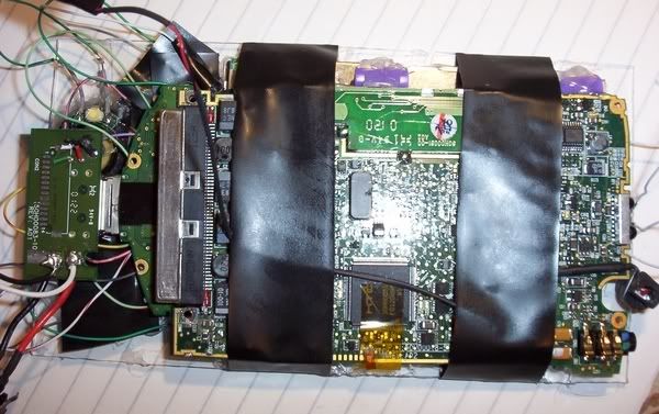
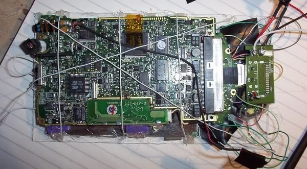
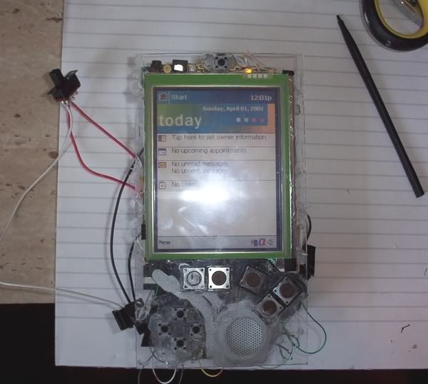
Wiring done (I also wired the speaker up too, after taking these pics)
Electrical tape over contacts to prevent a short
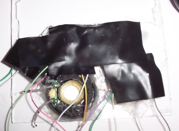
Assembled
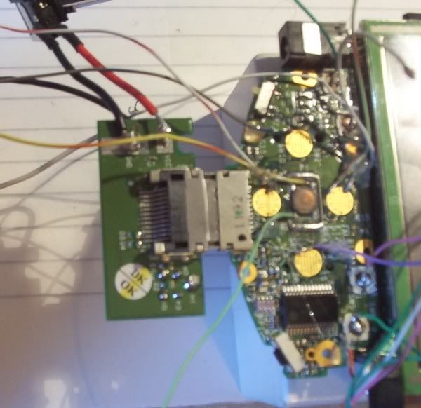
To prevent the ribbon cable moving, screen has some small blobs of hot glue to keep it in place, and I wrapped some electrical tape across the case front and mobo to stop it moving:
Success! Through the configuration screens first time! To the right of my hand on the desk are the 4 AA's powering the system at the moment. Ignore the line on the screen, that is not a scratch, but a strand of hot glue!
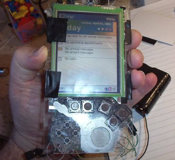
I tested each tact switch in turn, all work fine!
Removed electrical tape and replaced with wires, hot glued in place near edges of case, as per pic.
Plenty of work to do tomorrow on this project!
Wiring done (I also wired the speaker up too, after taking these pics)
Electrical tape over contacts to prevent a short
Assembled
To prevent the ribbon cable moving, screen has some small blobs of hot glue to keep it in place, and I wrapped some electrical tape across the case front and mobo to stop it moving:
Success! Through the configuration screens first time! To the right of my hand on the desk are the 4 AA's powering the system at the moment. Ignore the line on the screen, that is not a scratch, but a strand of hot glue!
I tested each tact switch in turn, all work fine!
Removed electrical tape and replaced with wires, hot glued in place near edges of case, as per pic.
Plenty of work to do tomorrow on this project!
-
bacteria
- Portablizer Extraordinaire
- Posts: 3984
- Joined: Fri Apr 20, 2007 12:14 am
- Location: Hampshire, UK
- Contact:
I am still bidding on e-bay for a cheap CF memory expansion packs, they have gone for several pounds - there are a couple more coming up in the next days; if I win one cheaply I may well include it in this project, but I have no intention to spend much on one of these expansion packs, after all I am going to hack it to bits and have no guarantee it will work afterwards, or it will fit properly inside my project.
Last edited by bacteria on Wed Nov 14, 2007 4:35 am, edited 1 time in total.
-
bacteria
- Portablizer Extraordinaire
- Posts: 3984
- Joined: Fri Apr 20, 2007 12:14 am
- Location: Hampshire, UK
- Contact:

I need 8 x AA's to give fantastic battery life. Why have about 3.5 hours when you can have about 10.5 hours?

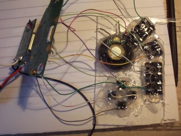
I decided to use three battery compartments to fit the 8 cells - 3+2+3. I had to solder and glue a new battery terminal connector to the negative terminal on the 2 cell compartment and snip off the wire which connected the positive to the negative on the 2 cell compartment to keep them separate. This meant I could have 3+1=4 cells, twice.
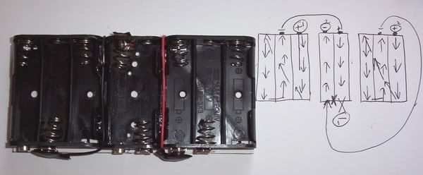
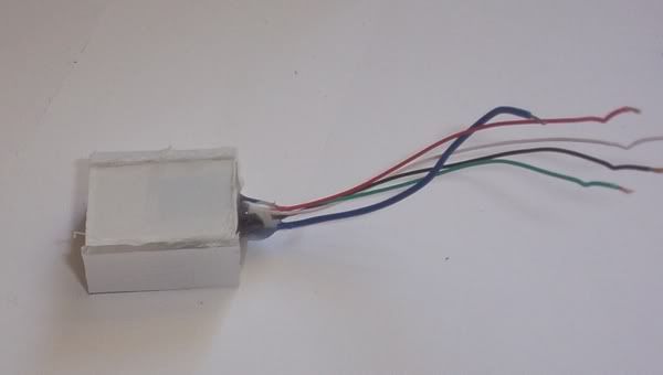
Battery pack
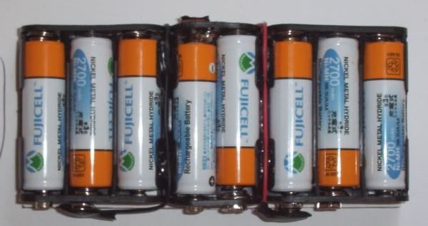
Wired it all up.
red = positive terminals (two battery packs in parallel)
brown = negative for above
yellow = switch for battery operation
green = mains in
Simple concept really; if mains is plugged in it will always run off mains, if the battery pack is then turned off, the PDA only runs on the mains; if the battery pack is on then the batteries will recharge whilst the system runs.
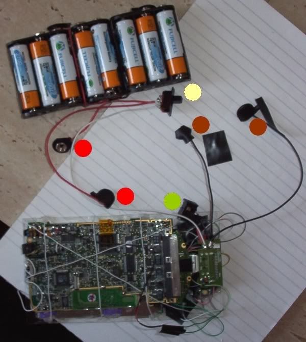
Ran system, worked first time past configuration screens and onto the system
At its thickest, it is now 40mm tall (allowing for case rear). This is why I was trying before to get the batteries inside the system
I have a dilemma:
Option 1:
Keep everything as it is, have the dimensions 159x91x40mm and keep the 8 cells for the 10.5 hours life on a full charge, however
Option 2:
Make the system only have 4 batteries, life of about 3.5 hours on a full charge, put the batteries on the sides of the screen (2 on each side) and have the dimensions about 159x119x27mm.
Do I have it slimmer, lighter and wider (3.5 hours life), or fatter, heavier and narrower? (long life)
I feel the balance leans more towards option 1 as being wider may look a little odd and it would be nice not to have to think "I have x minutes left" rather than forget about this altogether; although double the battery weight is a negative.
Thoughts?
While I decide, I can start to make the front of the case look pretty, although once I have finished the front I will need to have decided between option 1 and 2 above as then I need to make the sides.
-
bacteria
- Portablizer Extraordinaire
- Posts: 3984
- Joined: Fri Apr 20, 2007 12:14 am
- Location: Hampshire, UK
- Contact:
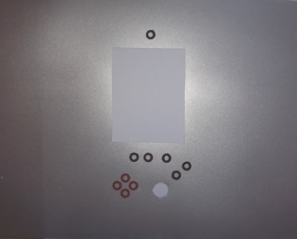
Designed template for the front case. It doesn't matter that I did it on the edge, it will be cut out more centrally on the PVC sheet.
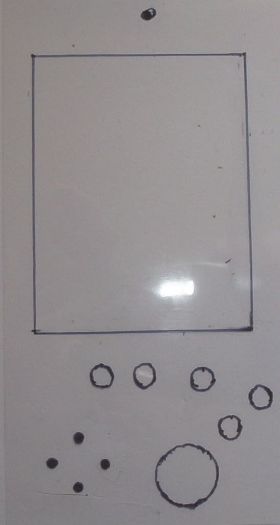
Fitted on the PDA, the marks on the previous pic are shown to be directly over the corresponding buttons and screen area. I don't need to cut out the holes for the buttons (I will cover that later), rather it is to represent where the button tops will go.
I reverse spray painted some PVC sheets before, in preparation for this stage.
The finish is lovely and even, and looks quite metallic. If you look on the right side of the sheet, you see that the sheet is a bit transparent still, I will fix that by either painting the case black so when the PVC goes on top it looks opaque, or paint on the PVC sheet for the same effect; or stick the PVC to a sheet of thick paper/thin card (160 gram) in place or use a self-adhesive label sheet - will need to experiment.
-
bacteria
- Portablizer Extraordinaire
- Posts: 3984
- Joined: Fri Apr 20, 2007 12:14 am
- Location: Hampshire, UK
- Contact:
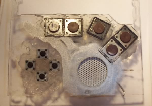
I am going to use spacer washers (normally used as spacers when installing a mobo into a computer) for the buttons, I bought them ages ago. They are porous so I can use a black marker pen to colour them (as per the top one in the pic) and I will put some coloured card behind them to give them a nice look (not decided if using black or a different one yet). These buttons will be glued onto the PVC sheet so the tact switches underneath will make good contact, yet also be invisible.
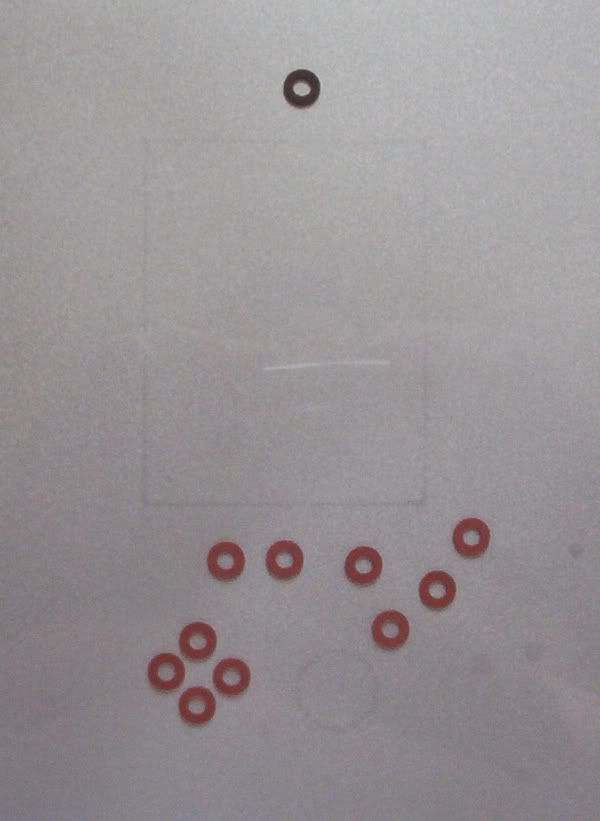
I haven't secured them in place yet of course, this is just to give an impression of what it will look like. The PVC sheet will lap over the sides, so will look really smooth (I just have the corners to worry about)!
Edit - oops, the one on the far right is an error - shouldn't be there!
The on/standby button at the top was central in my case, as was when I tried to stuff the AA's behind the PDA before, now it isn't as it also wasn't in the original PDA - it is central enough for the button to be located slightly to its side and still work, this way the button will look central! I will also adopt this method to make sure the direction keys (formally D-pad) are in a perfect line and exactly in the right position.
-
bacteria
- Portablizer Extraordinaire
- Posts: 3984
- Joined: Fri Apr 20, 2007 12:14 am
- Location: Hampshire, UK
- Contact:
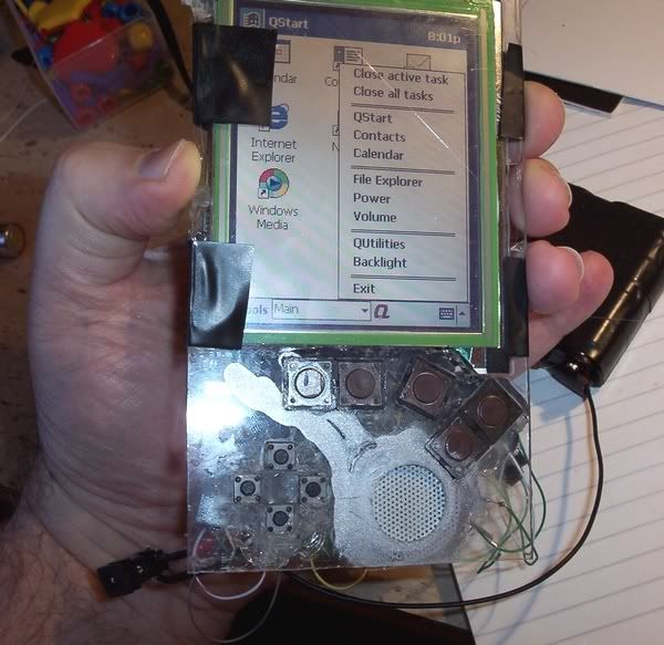
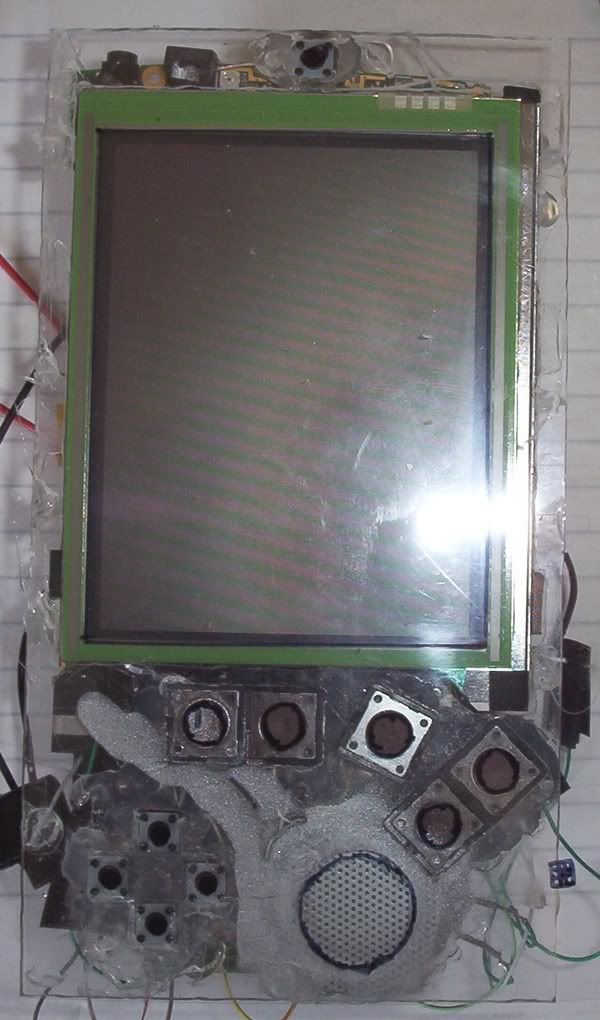
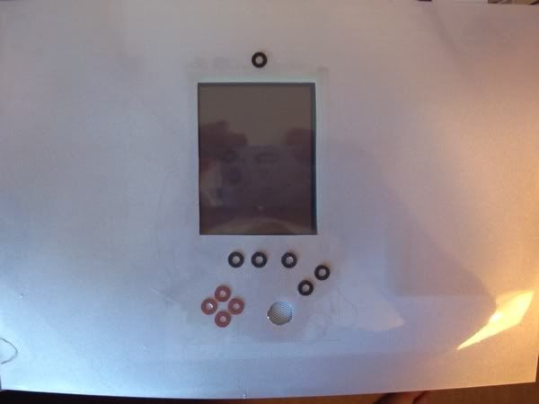
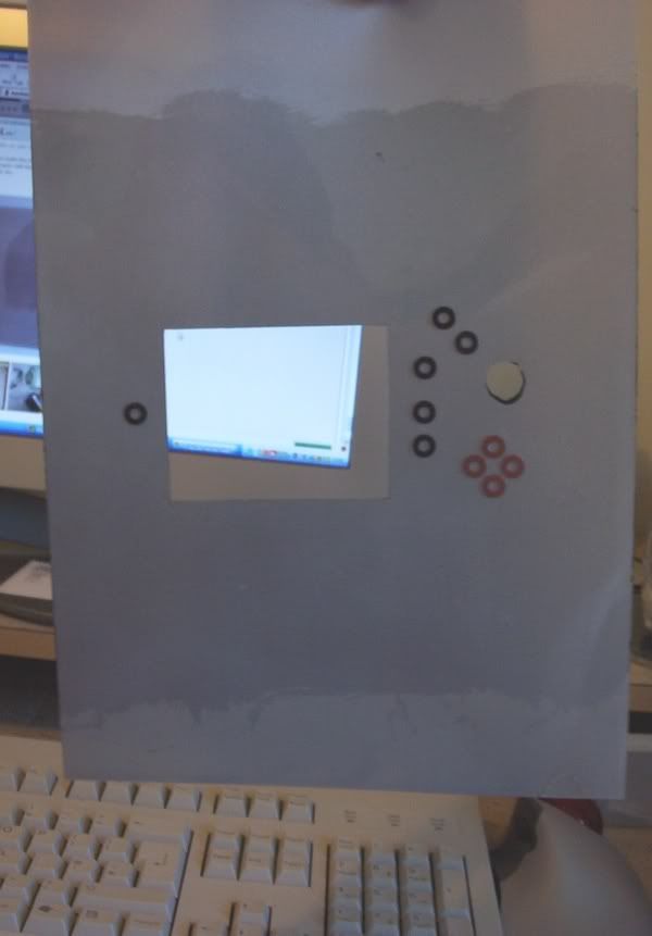
I decided silver was the best backing colour, I also decided having the holes between the washers felt far better and more positive to use than if the top is solid, so I left the ones for the direction buttons in their original colour and coloured the others black. I also cut the screen window out (the screen is touchscreen, so I don't want to have anything on top of it), and a crude cut-out for the speaker hole. Once the PVC sheet is on the PDA properly and securely, I will use my dremel to cut the speaker circle out exactly.
I then put it on the PDA, you can now see what the end product will look like - all be it flatter when glued in place. I think it looks nice!
I then put it on the PDA, you can now see what the end product will look like - all be it flatter when glued in place. I think it looks nice!
-
bacteria
- Portablizer Extraordinaire
- Posts: 3984
- Joined: Fri Apr 20, 2007 12:14 am
- Location: Hampshire, UK
- Contact:
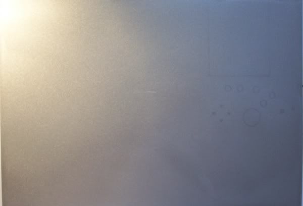
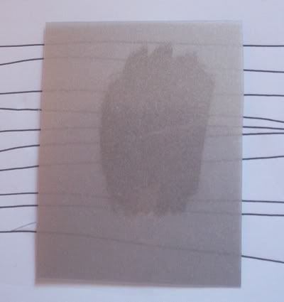
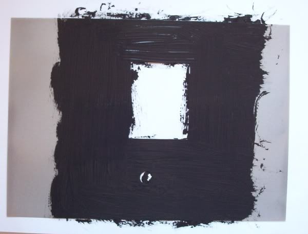
The best way to make the PVC opaque is to paint on the reverse side of the PVC sheet. For illustration, below is a scrap piece, which I painted in black on the reverse side, put it on paper with lines across (to show something from underneath), as you see, the painted bit is opaque. Job done! I need to paint the sheet now like this, and wait for it to dry.
example:
example:
-
bacteria
- Portablizer Extraordinaire
- Posts: 3984
- Joined: Fri Apr 20, 2007 12:14 am
- Location: Hampshire, UK
- Contact:
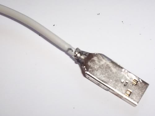
Time to hack a USB port.
I use the sandpaper attachment on my dremel to grind off the plastic sheath around an old USB cable (from a dead computer mouse) and get to its bareness. I don't have the space in the case to install the end of a USB cable - too thick and too long. By getting rid of the plastic sheath it leaves about 35% of the original thickness and by getting rid of the cable support at the back, I end up with a shorter USB connector, which will fit in my case fine.
I could have used a female USB for the case, but I have a spare male>female USB cable, so I thought I would use a male USB cable rather than buying a male>male one.
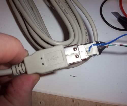
Stripped.
Metal surround removed. As it turned out I didn't have to, but did anyway, leaving enough for a female USB to connect.
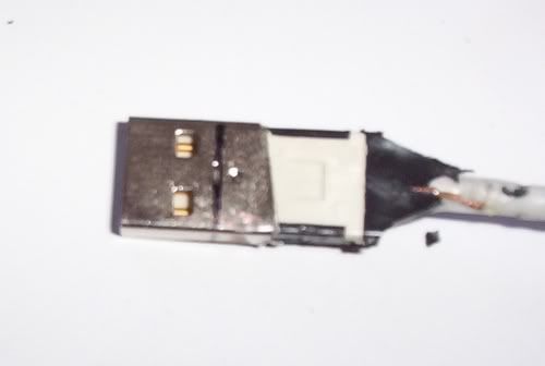
I have the plans (from research I did for my next project - GP2x mod), which show the pinout for a USB cable.
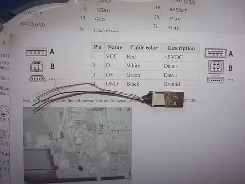
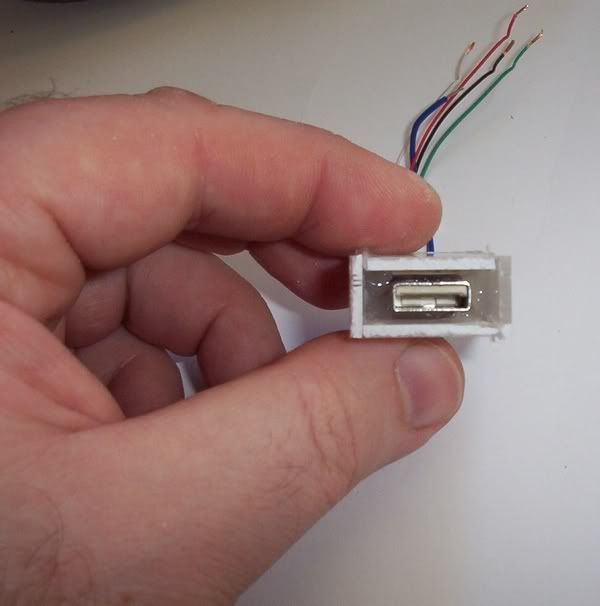
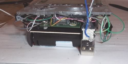
I marked out how far I need to allow the female connector to insert into the case. There is a fifth connection on a USB cable, the bare wire - this connects to the metal outside of the USB connectors, so I attached a wire for this in place as when I removed most of the outer metal casing it removed the contact to this metal.
You can see, it is the right size for the project now, I just need to wire it up.
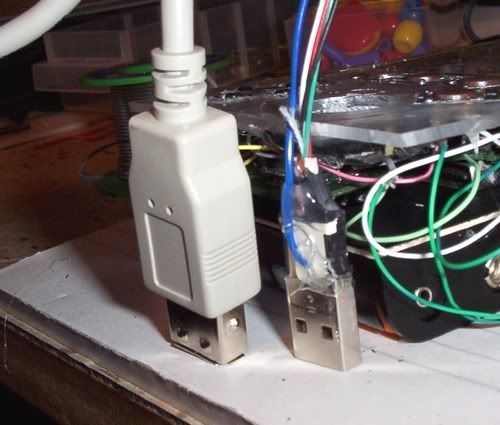
In comparison, I put the female connector next to my modded one, so you can see why I did what I did.
I use the sandpaper attachment on my dremel to grind off the plastic sheath around an old USB cable (from a dead computer mouse) and get to its bareness. I don't have the space in the case to install the end of a USB cable - too thick and too long. By getting rid of the plastic sheath it leaves about 35% of the original thickness and by getting rid of the cable support at the back, I end up with a shorter USB connector, which will fit in my case fine.
I could have used a female USB for the case, but I have a spare male>female USB cable, so I thought I would use a male USB cable rather than buying a male>male one.
Stripped.
Metal surround removed. As it turned out I didn't have to, but did anyway, leaving enough for a female USB to connect.
I have the plans (from research I did for my next project - GP2x mod), which show the pinout for a USB cable.
I marked out how far I need to allow the female connector to insert into the case. There is a fifth connection on a USB cable, the bare wire - this connects to the metal outside of the USB connectors, so I attached a wire for this in place as when I removed most of the outer metal casing it removed the contact to this metal.
You can see, it is the right size for the project now, I just need to wire it up.
In comparison, I put the female connector next to my modded one, so you can see why I did what I did.