illustriouschin - I have very steady hands. Cutting 2mm thick plastic with drill bits is an art. Try it before posting silly comments please. The pic on your monitor of the case front is about 4x the actual size of it, so naturally any tiny imperfections will be intensified by a factor of four (so a smooth dremelled surface will look a bit jagged). Copy one of my pics of the case front and paste it into your graphics editor and resize it so the case bottom is 82mm across (resize it to about 380 pixels across approximately if you use a 17" monitor), that will be a better illustration of its true size - as I said before, the only edges relevant to being straight are the D-pad cross, the speaker circle and the outer cuts, nothing inside cut away is relevant (eg screen cutout), as you will see when their components are glued in place. Wait and see the final result.
The notch you refer to is present on the PDA perimeter; it needs to go through the plastic case - see the first pic of page 1 and you will see the notch on the screen I refer to.
benol - No, leaving it clear will look horrible, like the case front does at the moment. The outer sheet of thin PVC will hide the ills and make it look pretty.
Skyone - I will only need to use some filler for the sides, I will need the sides to be slightly curved so as to not have sharp edges and corners, although at this stage I am not sure if I will make the sides out of plastic or wood. I haven't decided yet if the sides will be straight or sloping - maybe a mix between the two.
I should only need 4 screws to secure the case together at the rear and allow removal of the insides if any repairs are needed in the future.
Bacteria - Ipaq 3600 PDA resurrected, improved! *DONE*
Moderator: Moderators
-
bacteria
- Portablizer Extraordinaire
- Posts: 3984
- Joined: Fri Apr 20, 2007 12:14 am
- Location: Hampshire, UK
- Contact:
benol - I know what you mean, seeing the mobos and wiring in a system can look nice and interesting, as long as it doesn't detract from using the system; however the sides of the PDA screen are a bit ugly and securing the tact switches in place meant glue blobs which don't look nice. I want to conceal all this from view and make it not look too "homebrew".
I want the system to look as sleek as I can make it, including sloping sides, if I can manage it.
I want the system to look as sleek as I can make it, including sloping sides, if I can manage it.

-
bacteria
- Portablizer Extraordinaire
- Posts: 3984
- Joined: Fri Apr 20, 2007 12:14 am
- Location: Hampshire, UK
- Contact:
Update time.
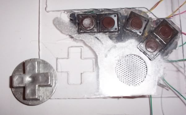
I dremelled down the NES D-pad to the minimum and used a tiny screwdriver to scrape off some of the trace so I could get a wire onto the contacts for the D-pad directions and common wire. I tried to place some solder onto the traces, had some success but not enough, so I put extra solder onto the wires and touched the top of the wire with the soldering iron when it was in place, this achieved a joint, all be it fairly weak. I tested the wires, all ok, then applied lots of hot glue to keep the wires in place so they wouldn't easily tug out by mistake. I also hot glued the rubber pad to the mobo to keep it in place. Normal glues don't work on rubber, hot glue does!
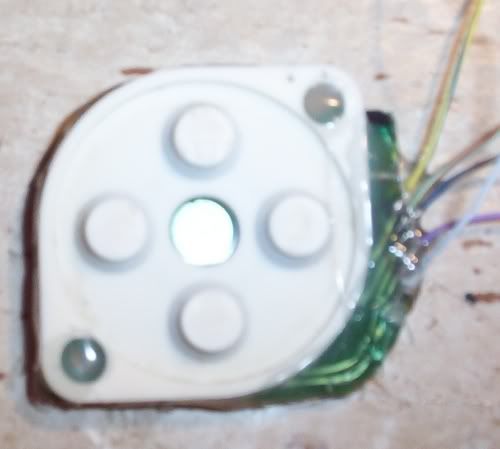
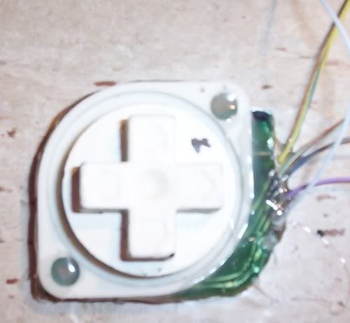
Image of D-pad with cross on top:
Next, I stripped some wires and soldered them to the tact switches
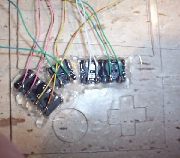
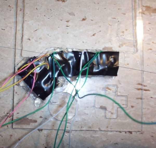
...and protected the metal from shorting with anything with electrical tape
I proceeded to put the first coat on the D-pad cross with silver spray paint. I would normally put some normal paint on as a base, however this D-pad already has this (the D-pad I had used before in my BigBoy Advance).
Next joy was to take a speaker grill from one of the PSone screens I stripped apart a while back and cut it to size
...and stuck it with hot glue in place on the case, making sure the cross pattern is about central
I then put the speaker (from a GBA before) in place and hot glued it in position, all around the side of the speaker
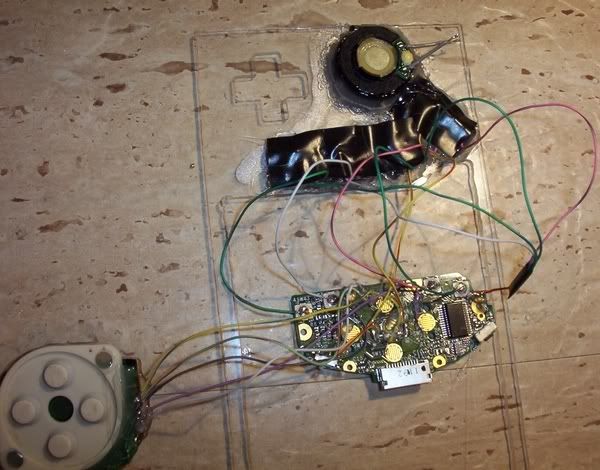
Front view, so far - all fits nicely:
One factor I hadn't thought about is that the D-pad takes height. I will do what I can to make sure it doesn't increase the height of my case, or if it does, by as little as I can get away with.
Once I have put a couple more layers of spray paint onto the D-pad cross, I can varnish it, then mount it on the D-pad (with hot glue of course) and then fix it permanently into the case. After that, I can wire up all the contacts and attach the screen in place.
benol - as I mentioned before, if this doesn't have an outer cosmetic covering this would look bad!! (now you see why!).
I dremelled down the NES D-pad to the minimum and used a tiny screwdriver to scrape off some of the trace so I could get a wire onto the contacts for the D-pad directions and common wire. I tried to place some solder onto the traces, had some success but not enough, so I put extra solder onto the wires and touched the top of the wire with the soldering iron when it was in place, this achieved a joint, all be it fairly weak. I tested the wires, all ok, then applied lots of hot glue to keep the wires in place so they wouldn't easily tug out by mistake. I also hot glued the rubber pad to the mobo to keep it in place. Normal glues don't work on rubber, hot glue does!
Image of D-pad with cross on top:
Next, I stripped some wires and soldered them to the tact switches
...and protected the metal from shorting with anything with electrical tape
I proceeded to put the first coat on the D-pad cross with silver spray paint. I would normally put some normal paint on as a base, however this D-pad already has this (the D-pad I had used before in my BigBoy Advance).
Next joy was to take a speaker grill from one of the PSone screens I stripped apart a while back and cut it to size
...and stuck it with hot glue in place on the case, making sure the cross pattern is about central
I then put the speaker (from a GBA before) in place and hot glued it in position, all around the side of the speaker
Front view, so far - all fits nicely:
One factor I hadn't thought about is that the D-pad takes height. I will do what I can to make sure it doesn't increase the height of my case, or if it does, by as little as I can get away with.
Once I have put a couple more layers of spray paint onto the D-pad cross, I can varnish it, then mount it on the D-pad (with hot glue of course) and then fix it permanently into the case. After that, I can wire up all the contacts and attach the screen in place.
benol - as I mentioned before, if this doesn't have an outer cosmetic covering this would look bad!! (now you see why!).
-
bacteria
- Portablizer Extraordinaire
- Posts: 3984
- Joined: Fri Apr 20, 2007 12:14 am
- Location: Hampshire, UK
- Contact:
Before I finish for the day, posting this - I found the common connection for the D-pad with my multimeter, so I wired that (white wire) to the mobo and the four other direction wires. I still have a few more connections to wire up, will hopefully do this tomorrow.
This is very precise work, putting a tiny blob of solder onto the contact area, then putting a wire on top and touching it quickly with the soldering iron to join the wire to the joint; then hot glue the wire in place so it doesn't detach if tugged lightly.
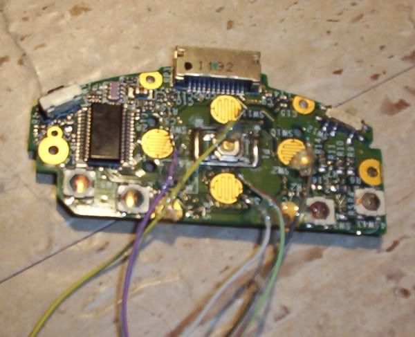
Four wires done, six to go! Let's hope everything works when it is all rigged up, it should do, but let's face it, sometimes things don't work even if there is no logical reason they shouldn't! I can't test until all the wiring is done.
This is very precise work, putting a tiny blob of solder onto the contact area, then putting a wire on top and touching it quickly with the soldering iron to join the wire to the joint; then hot glue the wire in place so it doesn't detach if tugged lightly.
Four wires done, six to go! Let's hope everything works when it is all rigged up, it should do, but let's face it, sometimes things don't work even if there is no logical reason they shouldn't! I can't test until all the wiring is done.
-
jeffslot
- Portablizer Extraordinaire
- Posts: 853
- Joined: Wed Jun 01, 2005 6:26 am
- Location: PA
- Contact:
Bacteria,
1st off I'm big fan of your inspiring work. Also I hate when people (especially people that haven't tried any of this stuff) add negative comments.
I do have a question that I don't understand & hope you can explain it to me (also this should allow me to be notified when this topic is updated),
I always though that on tact switches you needed to wire up any two diagonal facing leads, but in your picture it looks like you did ones on the same side.
I'm probably not understanding something, so please clue me in. Thanks & keep up the great work!
Jeff S.
The diagonal rule isn't really necessary. Everyone says it because manufacturers don't always have the pins the same, so diagonal is just a foolproof solution.jeffslot wrote:I do have a question that I don't understand & hope you can explain it to me (also this should allow me to be notified when this topic is updated),
I always though that on tact switches you needed to wire up any two diagonal facing leads, but in your picture it looks like you did ones on the same side.
Code: Select all
l- -l
-
bacteria
- Portablizer Extraordinaire
- Posts: 3984
- Joined: Fri Apr 20, 2007 12:14 am
- Location: Hampshire, UK
- Contact:
Hi jeffslot, nice to hear from you, been a while!
Thanks for saying you like my work and find it inspirational, it means a lot to me. I agree with you, there is no need for negative comments for the sake of it or downright stupid postings we get sometimes from "people that haven't tried any of this stuff"; forums tend to cater "for all elements" I suppose, it is its strength and its weakness. You and I are of "The older element" on this forum, so we have a better understanding of people's feelings and aspirations and prefer to encourage others rather than trying to deflate them. It's all down to maturity.
In regards to your query on tact switches, you can connect via diagonals, no problem; or via the two contacts next to each other (as I do) - not opposite sides though, otherwise the contact is permanently on! Personal choice, result is the same. I must confess I didn't think about connecting them via diagonals, every tact switch I have tried, including the ones on the mobo on the project, work with the contacts next to each other, so that is why I do likewise with my soldering.
I know my techniques are unusual at times, that is because I am self taught, I do research; the rest is down to logic, imagination, trial and error. If it works, that is what matters, not if it is the conventional method! Making useful working things out of whatever is to hand is a talent I have always had and that skill has been useful in my modding - look at my Nintendo 64 Advance project.
It is a good thing I have steady hands, placing a spot of solder onto contacts under 1mm in size needs accuracy!
On a different note, I found it interesting that a review of the latest type of Ipaq was saying that that model achieves "exceptional battery life" of 6 hours, with screen on low brightness and wi-fi off (using old wi-fi protocol so low security anyway); pah - I can get 10.5 hours on high brightness screen - I would probably get about 12-13 hours on low brightness level - double the amount!!
One thing I discovered, connecting my wires to the traces on the NES controller mobo gives less electrical signal; not enough to make my multimeter beep to indicate contact; when I use a home-made contact test (a 3v battery, with a LED connected, two clips connected to wires - make a contact and the LED lights) I get medium bright light, so the signal is clearly ok, hopefully enough - I will know better when the PDA is wired up and booted. If it isn't enough signal I will need to see how I can improve it.
-
illustriouschin
- Posts: 119
- Joined: Fri Feb 09, 2007 12:42 am
-
bacteria
- Portablizer Extraordinaire
- Posts: 3984
- Joined: Fri Apr 20, 2007 12:14 am
- Location: Hampshire, UK
- Contact:
illustriouschin - old Chinese proverb - "It is better to keep quiet and let people think you are an idiot rather than speaking and proving it".

As I posted earlier on, the perspex I am using on this project is a skeleton and not the outer surface, so getting a glass-smooth surface is a waste of time. The 6 thou thick PVC will be the outer skin; it will also wrap around the sides. Commercially made products, like remote controls, game controllers, etc are made of plastic with holes cut out, and open them up you sometimes find hot glue holding parts in place, and bits of plastic acting as levers. The point is that it is what you see (the exterior) that is important. Most people don't open things up so don't know the difference.
Before you post any more (please don't feel you need to), how about making something useful yourself, then you could make a useful contribution to this site. Perhaps then when you get some silly comments posted on your topic you will stop doing it to other people. (See first paragraph in this posting)...
Well, a suggestion for the next time you need to solder something really small;
You should use some flux on the contacts or at least the wire. I use it all the time, even with very small connections. You just put it on the joint, and then solder like usual. I don't use the pastey plumber flux- that stuff is hard to work with because it's pastey, not to mention it stinks when you solder with that kind of flux, and isn't so good for your lungs. I use this liquid gel flux, it's clear and resembles hand-sanitiser, but smells different. It doesn't make nasty smoke when you solder it, and what flux does is it makes the solder stick really good. Even on small connections. And the best part about flux is it's not conductive, so you don't need to worry about it if you spill some where it's not supposed to go on the board, you can just ignore it or wipe it up afterwards. That does not mean that using the flux makes your joints less conductive. When the flux heats up with the soldering iron, it melts/burns away, leaving a perfectly clean and prepared surface, which the solder bonds onto really really well.
The flux I use I found at a stained glass supply shop. It makes my projects so much easier.
Emulation isn't accurate. There is no substitute for real hardware!
-
bacteria
- Portablizer Extraordinaire
- Posts: 3984
- Joined: Fri Apr 20, 2007 12:14 am
- Location: Hampshire, UK
- Contact:
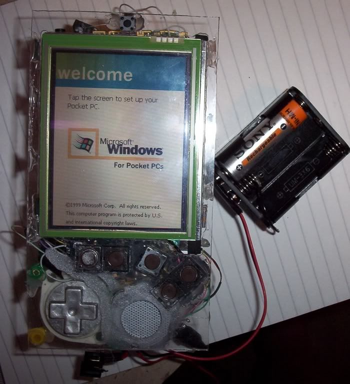
Made lots of updates, decided as things were a bit fiddly that I would crack on and get it all working, then document it. Here we go:
Completed the wiring. The centre tact switch on the mobo needed careful soldering, however the other 4 tact switches on the mobo were easy, they shared a common wire, the other wire could be soldered straight to the top (metal) part of the switch.
Everything assembled, screen in place too. I had some plastic beads (from a kiddies type necklace set I got for about £1, contained a couple of hundred of the things!), they make great posts to hot glue things in place, like the D-pad in the pic. BTW - I haven't straightened the PDA mobo yet, will do.
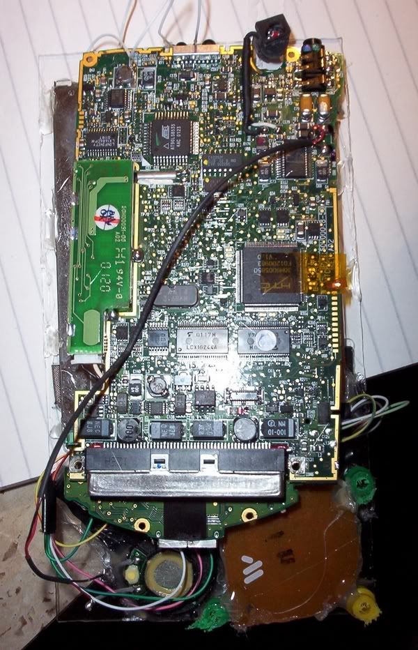
Here you can see the screen in place, I had to dremel out some tiny notches in the sides of the case so the screen would go through properly before hot gluing it in place. The screen is completely flat to the sides of the case, as planned.
I then rigged up a set of the batteries, all fired up fine! The only tact switch I have tested is the on/standby switch, tomorrow I will test the D-pad and the other 5 tact switches. Assuming they all work, I can progress and make it look pretty (it looks bad at the moment). I hope all buttons work, otherwise I have to take it apart again.
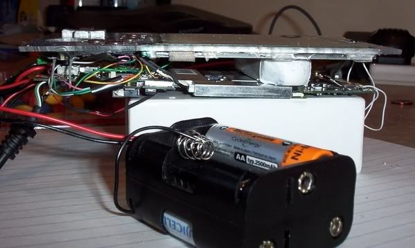
One consideration: because the wiring takes space, and the D-pad has made me have to raise the height of the PDA mobo (if I had continued to have all the 8 batteries on top of the PDA mobo), I decided to use the gap between the screen and the mobo for 4 batteries (in pic I used an eraser to prove the point) and have 2 batteries on the left and right sides (total of 8 in case). I will not use battery packs, I will make my own and make sure they are well sealed in electrical tape as otherwise I would get a short.
Having batteries on the sides will help me anyway, as I wanted sloping sides, and the batteries already have slopes pre-done! The PDA will be well balanced too as 4 batteries will be on the sides and the other 4 in the middle.
I can have the case height in total only 25mm high, which is far lower than I originally thought. This is only a mere few millimeters higher than the original PDA; in fact, taking into account the difference between the height of the original battery against the AA's, I have actually reduced the overall height!! If you take into account the Ipaq normally has to use an "Expansion pack" to add extra power, which doubles the Ipaq size, I think I have made a real achievement in size.
Completed the wiring. The centre tact switch on the mobo needed careful soldering, however the other 4 tact switches on the mobo were easy, they shared a common wire, the other wire could be soldered straight to the top (metal) part of the switch.
Everything assembled, screen in place too. I had some plastic beads (from a kiddies type necklace set I got for about £1, contained a couple of hundred of the things!), they make great posts to hot glue things in place, like the D-pad in the pic. BTW - I haven't straightened the PDA mobo yet, will do.
Here you can see the screen in place, I had to dremel out some tiny notches in the sides of the case so the screen would go through properly before hot gluing it in place. The screen is completely flat to the sides of the case, as planned.
I then rigged up a set of the batteries, all fired up fine! The only tact switch I have tested is the on/standby switch, tomorrow I will test the D-pad and the other 5 tact switches. Assuming they all work, I can progress and make it look pretty (it looks bad at the moment). I hope all buttons work, otherwise I have to take it apart again.
One consideration: because the wiring takes space, and the D-pad has made me have to raise the height of the PDA mobo (if I had continued to have all the 8 batteries on top of the PDA mobo), I decided to use the gap between the screen and the mobo for 4 batteries (in pic I used an eraser to prove the point) and have 2 batteries on the left and right sides (total of 8 in case). I will not use battery packs, I will make my own and make sure they are well sealed in electrical tape as otherwise I would get a short.
Having batteries on the sides will help me anyway, as I wanted sloping sides, and the batteries already have slopes pre-done! The PDA will be well balanced too as 4 batteries will be on the sides and the other 4 in the middle.
I can have the case height in total only 25mm high, which is far lower than I originally thought. This is only a mere few millimeters higher than the original PDA; in fact, taking into account the difference between the height of the original battery against the AA's, I have actually reduced the overall height!! If you take into account the Ipaq normally has to use an "Expansion pack" to add extra power, which doubles the Ipaq size, I think I have made a real achievement in size.