The Retro64 Worklog. NEWS: Finished! Got nice pics!
Moderator:Moderators
-
deviouskoopa

- Posts:144
- Joined:Tue Dec 30, 2008 2:19 am
- Location:Virginia Tech
- Contact:
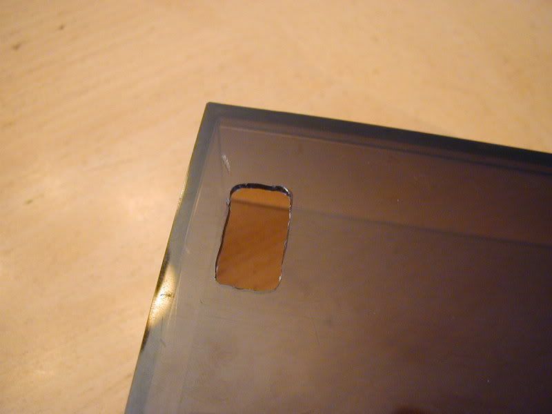
Man, don't post in 2 days and the topic gets bumped halfway down the page!  I tested out my new Dremel bit the other day, it works great. If you're interested, it's called a "High Speed Cutter Bit". It works great on the plastic. Here is a literal 5-minute job, cutting out a Z-Button hole on the scrap piece of plastic:
And with the button in it:
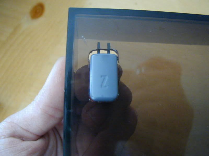
As you can see, it's a bit too big lengthwise, but otherwise a good fit. Keep in mind I seriously spent five minutes on this, and just a bit more sanding it. This was just a quick test.
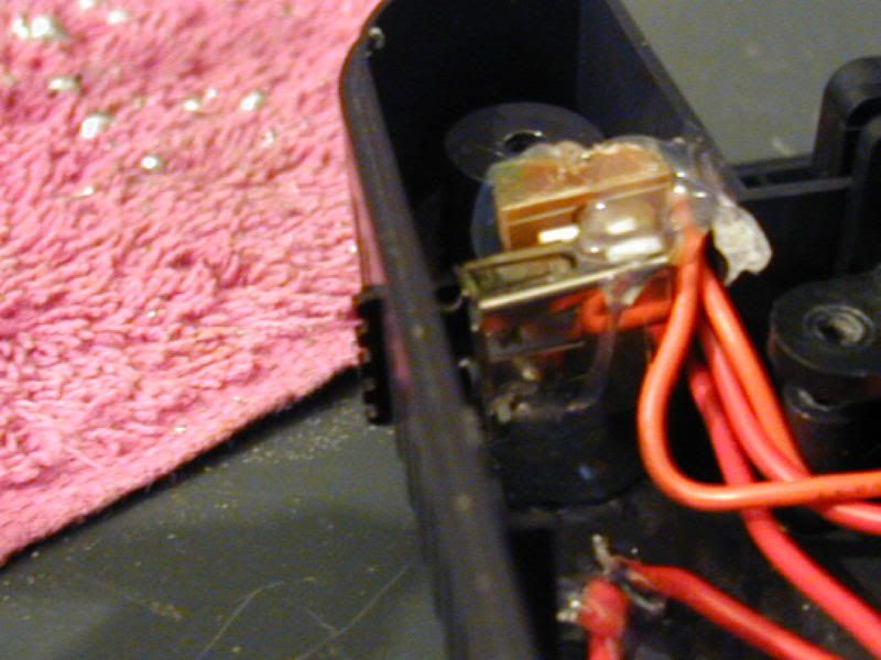
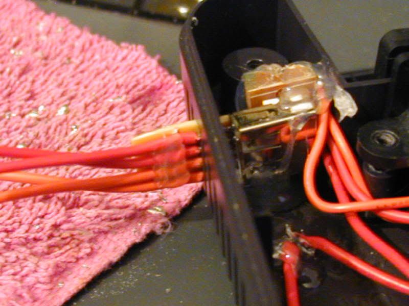
I got the battery charger modified to have a charge port on it. Here it is:
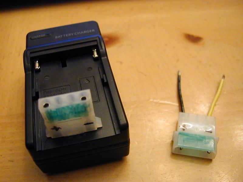
Yes, that's a hard drive power cable. It was the only thing I had on hand, plus I wanted to make sure the only thing you could plug into it was the correct cable. There will be a unique plug at the portable end, too.
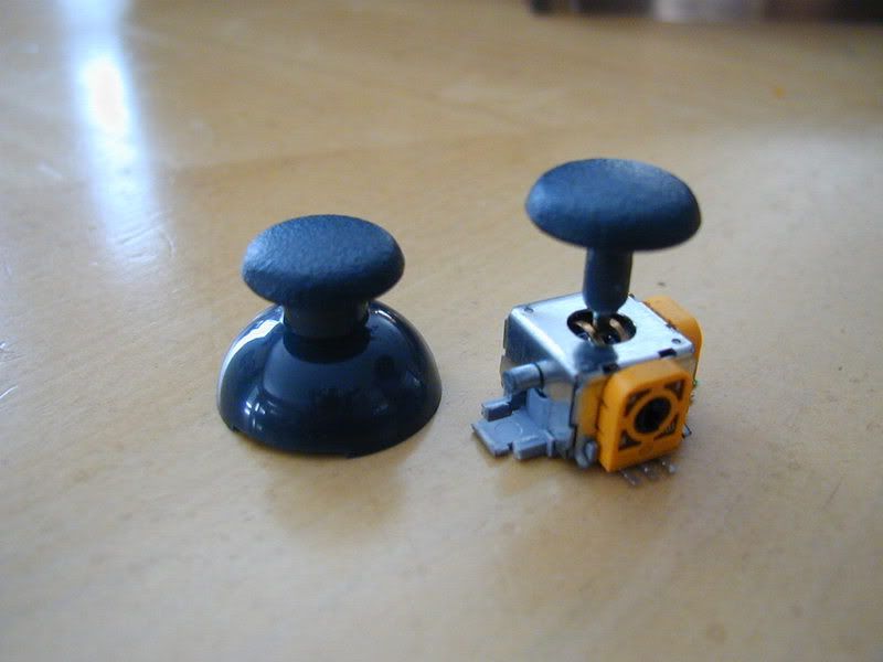
I also made the joystick. The actual joystick assembly is from a third party PS2 controller, as is the thumb stick. On the left is the unmodified thumb stick and on the right is the cut-down one. I didn't want the thumb stick "shield", so it was cut away. The joystick will sit right up against the inside of the case.
Just a heads-up, I'm going on vacation until Saturday, so there won't be and updates during that time. Thank you for your understanding.
And with the button in it:
As you can see, it's a bit too big lengthwise, but otherwise a good fit. Keep in mind I seriously spent five minutes on this, and just a bit more sanding it. This was just a quick test.
I got the battery charger modified to have a charge port on it. Here it is:
Yes, that's a hard drive power cable. It was the only thing I had on hand, plus I wanted to make sure the only thing you could plug into it was the correct cable. There will be a unique plug at the portable end, too.
I also made the joystick. The actual joystick assembly is from a third party PS2 controller, as is the thumb stick. On the left is the unmodified thumb stick and on the right is the cut-down one. I didn't want the thumb stick "shield", so it was cut away. The joystick will sit right up against the inside of the case.
Just a heads-up, I'm going on vacation until Saturday, so there won't be and updates during that time. Thank you for your understanding.

-
eurddrue

- Senior Member
- Posts:2367
- Joined:Fri Jul 18, 2008 1:26 pm
- Location:I am so caught up in real life I have to be done for a while. I'll still check in but dontexpectmuch
- Contact:
you still would have won your screen because you bid first... you do know that right?
and it shocked me too that your name isn't mario
and it shocked me too that your name isn't mario
Banned indefinitely if you desperately need to contact me STOPPHONESPAMPLOX Please dont be a dick and call for something random like "HEY YURDRUE DOO U HAZ SPAM?"
wallydawg wrote:I think we should check to see if you can withstand 220 voltschainfire95 wrote:220V I believe
-
eurddrue
- Senior Member
- Posts:2367
- Joined:Fri Jul 18, 2008 1:26 pm
- Location:I am so caught up in real life I have to be done for a while. I'll still check in but dontexpectmuch
- Contact:
I have that charger! except I use mine for the actually battery...
Banned indefinitely if you desperately need to contact me STOPPHONESPAMPLOX Please dont be a dick and call for something random like "HEY YURDRUE DOO U HAZ SPAM?"
wallydawg wrote:I think we should check to see if you can withstand 220 voltschainfire95 wrote:220V I believe


bacteria wrote:Mario - if you don't want to see the joystick itself, you could put a thin layer of fabric under the cut-out joystick cap; that would conceal the guts from view. Just a thought.
Good idea. I might use a piece of plastic, too.
How dare you call my rectangle a globby square!marshallh wrote:Get some files! Spend some time with one, you can make that button hole look really good. It'll turn from a glob-shaped square to a sharp rectangle.
I'd be fine spending an hour sanding it, but I can't draw a good template. Like, you know you have to draw the lines you want to cut inside. I do a horrible job. It's hard to follow them.
When I make holes, I use a drill first and then when I know its still too small but almost as big as the button, I switch to a file or sandpaper on a popsicle stick and just expand it slowly. and I keep putting the button up to it to see where I need to expand until it's a perfect shape for the hole. it's slow going but comes out nice.
It takes a big man to cry, but it takes a bigger man to laugh at that man.
Ridonkulous
Ridonkulous
-
schmellyfart

- Portablizer Extraordinaire
- Posts:1151
- Joined:Sun Mar 05, 2006 8:29 pm
- Steam ID:schmellyfart
- Location:Gilbert, AZ
- Contact:
Thats what I did for my snes portable. Unfortuantely I only had a dremel at the time so I used that instead of a file. Same technique though, just file it until the button fits.collinE wrote:When I make holes, I use a drill first and then when I know its still too small but almost as big as the button, I switch to a file or sandpaper on a popsicle stick and just expand it slowly. and I keep putting the button up to it to see where I need to expand until it's a perfect shape for the hole. it's slow going but comes out nice.
-
bacteria

- Portablizer Extraordinaire
- Posts:3984
- Joined:Fri Apr 20, 2007 12:14 am
- Location:Hampshire, UK
- Contact:
I was going to do that on my PSone project, if I couldn't make the stock joystick cap fit - it does, with about 1/2mm clearance, so I didn't need to in the end.Mario wrote:bacteria wrote:Mario - if you don't want to see the joystick itself, you could put a thin layer of fabric under the cut-out joystick cap; that would conceal the guts from view. Just a thought.
Good idea. I might use a piece of plastic, too.
As to making button holes, etc - I use a drill to get to about 2mm from the edges of the hole, then use small files to remove the rest. Cheap files are fine, I got 5 for £3.50 and some others even cheaper - they have small round ones, square, flat and rounded ones - work a treat!

Here's a neat update for you. First of all, the highlights. You know how the supposed mA draw for the N64 is relatively high? It was thought the 12v line drew 800mA and the 3.3v line 1.5A with the jumper pack, 2.0A with the expansion pack? Well, I have information that says otherwise!
I took a trip to RadioShack today and bought a new digital multimeter. It can measure current up to 10A, so I decided to test the N64s REAL amp draw. Well, here it is:
The JP x2.5 and EP x2.5 mean the overclocked speed. I installed a switch on my N64 to have the CPU clock speed at either x1.0 (factory default) and x2.5.
Now, the conclusion. This is crazy! The total amp draw was thought to be 2.8A with the expansion pack. I measured 1.4A with the expansion pack. That's half the amp draw!
Here are my speculations. The draw on the 12v line is 110mA, no matter what. It handles the audio mixing and something else, but I can't remember what it is. The 3.3v line is the main CPU line, so the draw on it fluctuated at most by about 100mA during play. The values up there are the averages.
With the expansion pack, the CPU line drew 150mA more than the jumper pack on a game that did not need it, SM64. With DK64, it drew 220mA more.
When you raise the CPU multiplier, the amp draw increases by about 125-200mA, which makes sense.
So overall, the amp draw of the N64 is much less than was thought. I'll go update my Console Voltage/mA Draw thread.
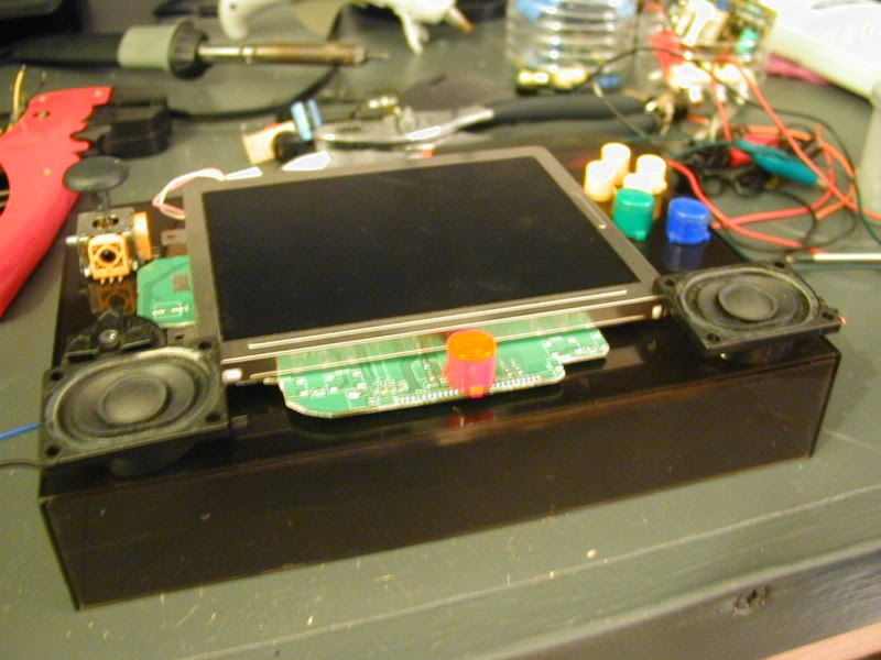
Now, another update. I have revised the button layout on the front of the case. The drawing i had earlier was just where I wanted the buttons; looking at the screen board I see that it won't quite work that way.
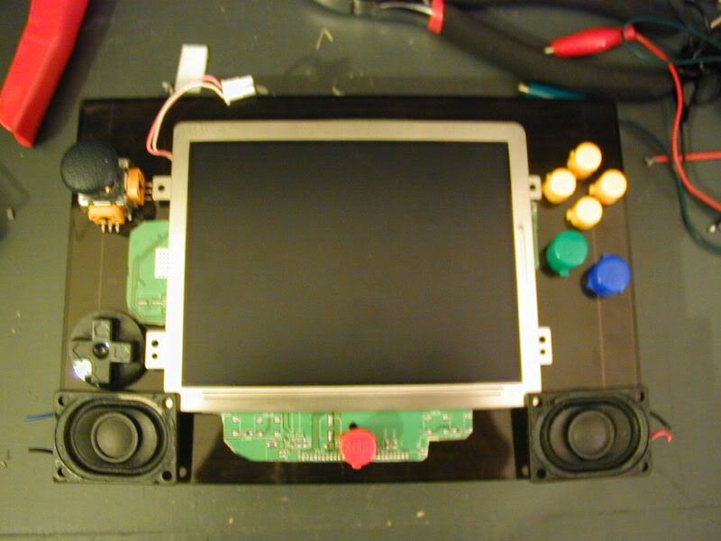
And without the screen board:
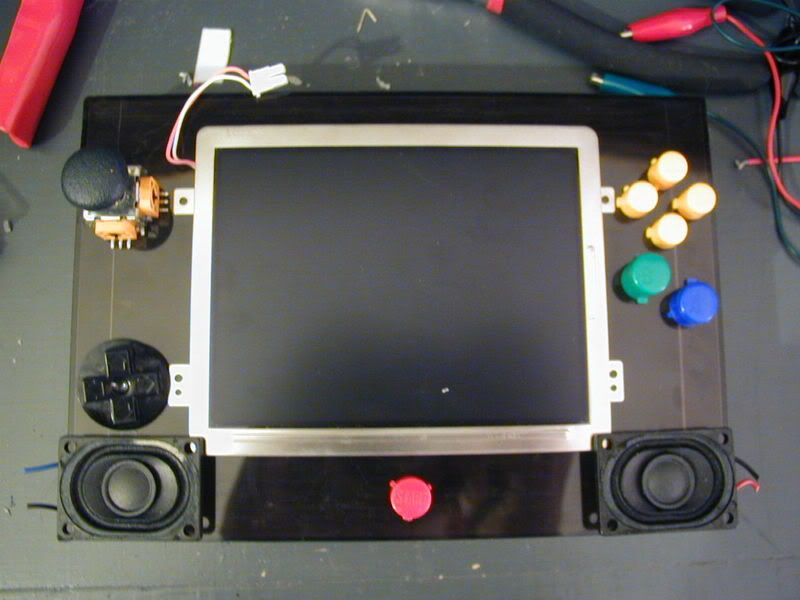
The only thing different is the D-Pad had to move down a bit, but the rest is the same.
By the way, here is the setup I made for testing the amp draw of my N64. As you know, to measure current draw, the multimeter has to be in series with the voltage line. Since there are 2 voltage lines, that means I need 4 connections. First I cut the traces for the lines. I then used a USB port stuck behind the side vents for the port:
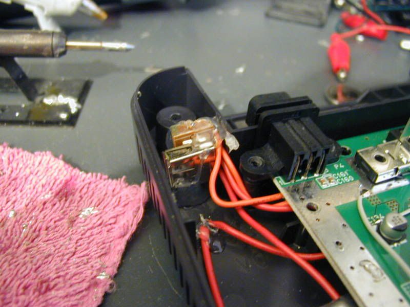
The voltage lines are disconnected with just the USB port; it needs a jumper to operate. This jumper is shown on the top, painted black so it blends in with the N64s case:
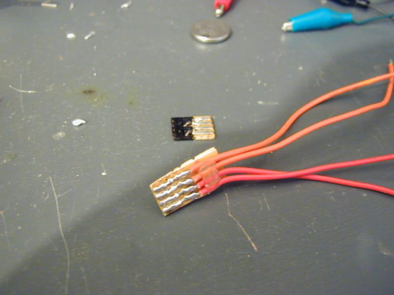
The lower thing with the wires is where I attach my multimeter for current testing. When not testing, the jumper must be installed:
And here is the tester:
That's all for tonight. Any questions, just ask.
I took a trip to RadioShack today and bought a new digital multimeter. It can measure current up to 10A, so I decided to test the N64s REAL amp draw. Well, here it is:
Code: Select all
Cartridge: Super Mario 64

           Jumper Pack   Expansion Pack     JP x2.5   EP x2.5

3.3v Line:   1.100 A        1.250 A          1.2 A    1.450 A

12v Line:    110 mA          Same            Same      Same

Cartridge: Donkey Kong 64 (Requires Expansion Pack)

            Expansion Pack   EP x2.5

3.3v Line:     1.320 A      1.450 A

12v Line:      110 mA        Same
Now, the conclusion. This is crazy! The total amp draw was thought to be 2.8A with the expansion pack. I measured 1.4A with the expansion pack. That's half the amp draw!
Here are my speculations. The draw on the 12v line is 110mA, no matter what. It handles the audio mixing and something else, but I can't remember what it is. The 3.3v line is the main CPU line, so the draw on it fluctuated at most by about 100mA during play. The values up there are the averages.
With the expansion pack, the CPU line drew 150mA more than the jumper pack on a game that did not need it, SM64. With DK64, it drew 220mA more.
When you raise the CPU multiplier, the amp draw increases by about 125-200mA, which makes sense.
So overall, the amp draw of the N64 is much less than was thought. I'll go update my Console Voltage/mA Draw thread.
Now, another update. I have revised the button layout on the front of the case. The drawing i had earlier was just where I wanted the buttons; looking at the screen board I see that it won't quite work that way.
And without the screen board:
The only thing different is the D-Pad had to move down a bit, but the rest is the same.
By the way, here is the setup I made for testing the amp draw of my N64. As you know, to measure current draw, the multimeter has to be in series with the voltage line. Since there are 2 voltage lines, that means I need 4 connections. First I cut the traces for the lines. I then used a USB port stuck behind the side vents for the port:
The voltage lines are disconnected with just the USB port; it needs a jumper to operate. This jumper is shown on the top, painted black so it blends in with the N64s case:
The lower thing with the wires is where I attach my multimeter for current testing. When not testing, the jumper must be installed:
And here is the tester:
That's all for tonight. Any questions, just ask.