sam_thornley wrote:Cool! awesome job

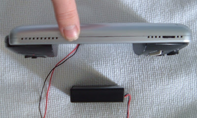
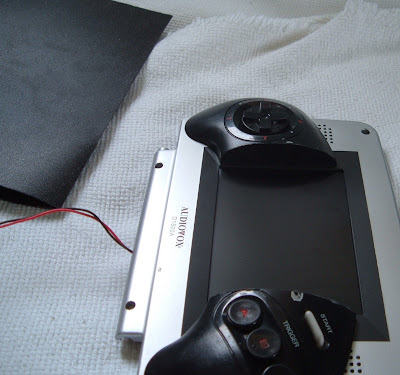
, I like how you've attached halves of the controller. I always prefer horizontal orientation with portables.

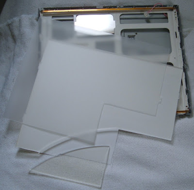
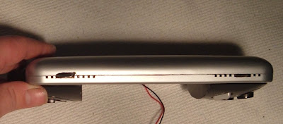
Yeah, I like horizontal, and this screen is pretty big actually, all 5 inches of it.
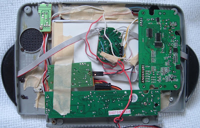
From what i can see theres no sound amp or speakers, to be added in the future maybe?
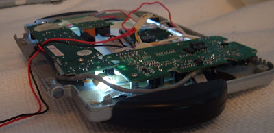
Yep, I put the right side of the controller completely covering the sound and bright wheels, and both headphone sockets

, so I need to cut down or relocate the sound board, I already freed the bright knob and moved it to the vents at the top of the screen.
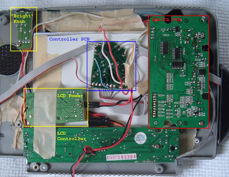
For the battery i'd recomend 4 AA's (5.8-6volts) as your screen uses the same Sharp video processor as the intec/hip gear, witch runs fine at 6v so you should be ok. The radica will run on any thing from 4-9 volts.
I am using NiMH, on the AAA and AA packs I get 5.25 volts fresh charged, and 4.98 as they settle in, I have to use rechargeables, so I am just going to get used to it or use 6 cells. (although as long as I am putting out close to 5 volts I am considering bypassing the voltage regs on the LCD and Radica, I just need a circuit that will make +12v and -12v to drive the LCD)
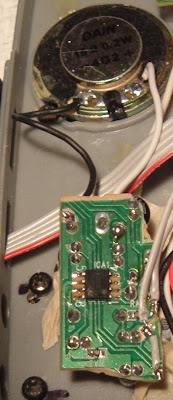
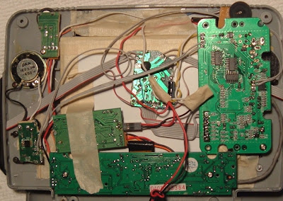
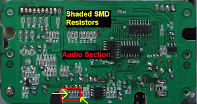
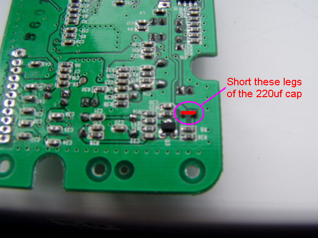
You also say that your screen "flickers" on some games. This may be because theres too many 220uf caps on the video line (one on the radica and one on your screen). I had the same problem on the game block (filckering on "bright images" like the sega intro on sonic 2 or 1). But its really quite easy to fix. Theres a 220uf cap in the video area of the radica PCB, on the under side just short the legs together. Heres a pic:
snip
Also you could mod the radica for s-video as your screen's Sharp video processor is capable of s-video.
Let us know how you get on...
I do want S-Video (Sonic 2 bleeds blue like a dying alien), but I can't find a picture of the mod, have you got one?
I will try bypassing that capacitor to clean up the signal (If I go S-Video should I bypass the amp too? I won't put an amp on the Luma line so why should there be one on the Chroma line? I plan to run dual shielded lines about 5-6 inches.)
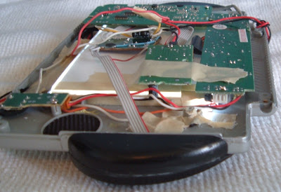
Nuts, I just went to town and forgot to pick up some new caps (10uf 25v) to replace the three I layed down flat

, oh well, maybe I will remember the next time I go, in a month

.
This project was because I was sick and wanted to see what I could build for $8 (the cost of the radica) using the junk laying around in my room. While I wait for my PC parts to come in (how does 95945 look even remotely like 91311?? Neither are even my confirmed Paypal ship too address

.)
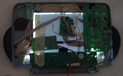
EDIT: Sound is almost in, it will be pretty nice.


