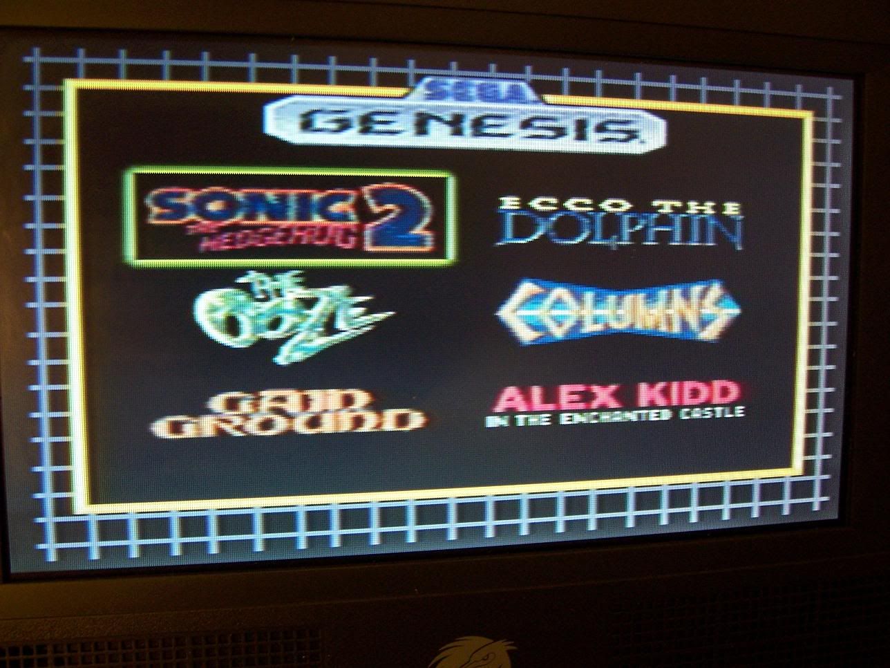
Okay, so I love the Radica and all, but lets face it....composite is ass. It's the biggest drawback to this awesome GOAC and ever since I saw 2 seperate video lines mixing when I first opened the unit (the 2 blue inductor chokes) I've been wanting to get Svid out of one.
I gave up on the work a while back for reasons I don't remember but finally went back to the project last night and successfully pulled S-video from the unit:
http://i18.photobucket.com/albums/b134/ ... posite.jpg
(that's original composite)
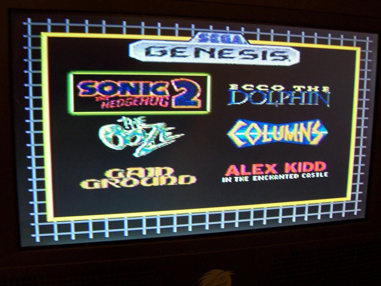
http://i18.photobucket.com/albums/b134/ ... caSvid.jpg
(that's S-vid)
You'll notice a difference even though it's not HUGE. I might be able to make it better with some tweaking but I think the GOAC doesn't output the purest S-video which is why there are still some minor cross-color artifacts. Still better than composite though, which is what I care about :)
I'll be posting a schematic and "how to" soon. The best method is to just get 2 Radicas though (one broken if you have it) so you can just use the amping circuit on one rather than building your own from scratch.
-Segasonicfan
Radica S VIDEO mod success ^_^
Moderator: Moderators
-
segasonicfan
- Moderator
- Posts: 516
- Joined: Fri Jul 23, 2004 3:57 am
-
segasonicfan
- Moderator
- Posts: 516
- Joined: Fri Jul 23, 2004 3:57 am
OK, here's a schematic of the mod I did, the cap values are unknown for the time being since they are SMD and I don't have a way to test the values right now :/ Most everyone is prob going to use another Radica for this circuit anyway.

The idea of the mod is pretty simple: Just keep everything the same on your original Radica but disconnect the Chroma signal. That way the two aren't mixed and you get a pure Luma signal.
All you do after that is amplify the separate C signal before sending it onto your TV. This is done through simple general purpose NPN transistor (I used the 2N5551 but any general purpose will do). Feed it through a standard 220uf cap and you'll have a nice strong Chroma signal to work with. Voila, 2 signals with 2 amps for S-video :)
I'll take pics of the board later for better instructions on the mod.
-Segasonicfan
-
bicostp
- Moderator
- Posts: 10491
- Joined: Mon Mar 07, 2005 5:47 pm
- Steam ID: bicostp
- Location: Spamalot
- Contact:
It's not RGB, but I suppose anything's better than Composite. 
I just wish i could get my folks to realize that. (We use the DVD player all the time, it has Component video, the TV accepts component video, we have a ton of RCA wires around, but it's hooked up through crappy ol' composite. )
)
How exactly do you test capacitance?
I just wish i could get my folks to realize that. (We use the DVD player all the time, it has Component video, the TV accepts component video, we have a ton of RCA wires around, but it's hooked up through crappy ol' composite.
How exactly do you test capacitance?
Twitter
http://www.pcwgaming.com" onclick="window.open(this.href);return false;
If you want a Dropbox account, please use my referral link
http://www.pcwgaming.com" onclick="window.open(this.href);return false;
If you want a Dropbox account, please use my referral link
-
segasonicfan
- Moderator
- Posts: 516
- Joined: Fri Jul 23, 2004 3:57 am
Yeah, sadly getting RGB from the Radica is impossible. The RGB encoder is built into the chip so there are no outputs to work with :(It's not RGB, but I suppose anything's better than Composite. Smile
With a Multimeter. Hardly any of the ones on the market test it from what I've seen, including my Fluke. The newer Flukes do though, I just have to lay down $100+ for one :/How exactly do you test capacitance?
-Segasonicfan
-
bicostp
- Moderator
- Posts: 10491
- Joined: Mon Mar 07, 2005 5:47 pm
- Steam ID: bicostp
- Location: Spamalot
- Contact:
Duh.segasonicfan wrote:With a Multimeter.How exactly do you test capacitance?
So I guess this means our really old one and the newer Rat Shack meter won't do the job?Hardly any of the ones on the market test it from what I've seen, including my Fluke. The newer Flukes do though, I just have to lay down $100+ for one :/
Twitter
http://www.pcwgaming.com" onclick="window.open(this.href);return false;
If you want a Dropbox account, please use my referral link
http://www.pcwgaming.com" onclick="window.open(this.href);return false;
If you want a Dropbox account, please use my referral link
-
segasonicfan
- Moderator
- Posts: 516
- Joined: Fri Jul 23, 2004 3:57 am
yea here is a quick question, why invest this time and frustration for improving a radica? I mean You personally have a -video modded CDX, I know it EATS batteries but the Radicas are they REALLY that big of an improvement over say a Genny3? (reminded that it can get RGB easily...)
On a more positive note, it does look good, much better that the composite (despite you saying it isn't a huge difference it is noticibly better)
On a more positive note, it does look good, much better that the composite (despite you saying it isn't a huge difference it is noticibly better)
I refuse to dignify myself with an intelligent and witty signature
-
project_failure
- Posts: 812
- Joined: Sun Dec 25, 2005 4:04 pm
- Contact:
-
sam_thornley
- Posts: 137
- Joined: Sat Mar 10, 2007 7:32 pm
- Location: Derbyshire, UK
- Contact:
I used this mod for my portable. It works fine, but i did'nt have to use an amping circuit for the chroma. I just hooked it up directly. I biult an amping circuit but it would'nt work, i just keypt getting a black and white picture (no chroma signal being sent). I recon that the GOAC outputs a chroma signal that is allready useable.

Hey Sam, I just saw the Gamebrick 2.0, very nice!
@segasonicfan, do you have the schematics any longer? They are blank, fileshack has nothing there
It is great news that it will work though, I have an S-Video taking Audiovox screen to put to good use (well it can actually take RGB, but if we got everything where would the fun in life be?).
Is it possible that the amp is for the A/V cable run and possible resistance in the A/V hookup? IE if we just hack it right to the input PCB of the LCD (less than 10 inches away, no connectors) it should be fine? Couldn't hurt to try I guess.