I recently acquired a 7" TFT LCD from a portable DVD player. Now before I get flamed all over the place for not reading the sticky, I've done some research on the encoder chip that the controller board uses and it can accept both composite video and analog RGB. However, I can't find any info on which pins on the IC are for inputting the various signals. The chip is a Sharp RB5P006AM. Does anyone have any ideas to help me figure this one out?
TIA,
Nick
*EDIT* I have the pinout for the rb5p006am encoder chip
Moderator:Moderators
Last edited by myersn024 on Wed Jan 10, 2007 3:09 pm, edited 1 time in total.
Well, after some dubious searching I decided to call Sharp and see if they would help me out. I had to talk to two different people, but I finally got the info I was looking for. Then after a little work taping things together to do a test run, I got TLOZ:ALTTP to play on the screen using composite video input. According to the info I got from sharp, this screen also accepts RBG and Y/C input. I don't have anything running either of those modes so I can't test it. They asked me not to distribute the documentation they sent me, but I'll be more than happy to post up the pinout of the chip if anyone wants.
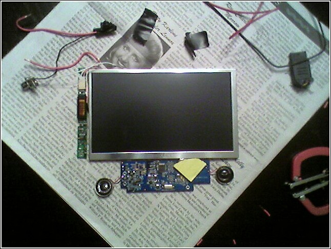
The only bad thing about the screen is that it doesn't have an audio amp bulit in. All those functions were taken care of by the DVD player mobo in the bottom part of the DVD player. It does have speakers attached to it, so a separate audio amp could be built and attached to the speakers that are already on the LCD controller board. The piece of paper in the picture below was put on a spot of adhesive to keep it from sticking to everything.
<img src=http://www.austinbull.com/pictures/innolux.JPG width=400>


I had to have some help holding all the contacts, so I didn't get a good look at it....but, I'm pretty sure it displays it stretched. I'm going to break out the soldering iron and attach some leads so I don't have to hold everything together with my fingers. Once I do I'll post back and let you know for sure.
Who knows. I found some simple info about the chip family on the internet, but I wasn't able to find the pinout. It took calling to get the chip map. When I first got the screen, I almost threw it away after reading that most portable DVD player screens weren't usable, but I kept it on the off chance that I might find a way to use it. I'm happy I did for three reasons. First of all, I didn't tear up a perfectly good portable DVD player for nothing. Second, it has better resolution than the pelican gameglass that I got a few days ago. And third, because it runs on extremely low voltage. The battery that came with the player was a 3000 mah lion, and on a full charge it could power the whole deal for almost two full DVDs.vskid wrote:I wonder what other screens could be used if we just asked the encoder chip manufacturer for help...
It took a little doing, but it is up and running now. Operating voltage will be a key factor in picture quality since there isn't a contrast or brightness setting. 10V is too high and 5V won't light the backlight. I'm guessing that 7.4 to 8.4 will be ideal. A brightness control could be rigged up since the backlight controller board's + and - pads are well labeled. The contrast will be a different story. However, from what I can tell it won't be a problem. As for the 16:9 aspect, it stretches normal NTSC video leaving a slight letterbox around the peripheral of the screen, but nothing annoying.
EDIT: some chips have special inputs for controlling the RGB settings. If you put a pot meter with the right value between the 2 correct pins you can control the contrast. But then again that's only with some chips.


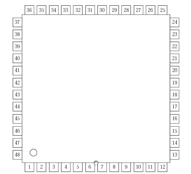
Sure thing. First thing first: Here's the layout of the chip with the pin numbers.
<img src=http://www.austinbull.com/pictures/pin_map.jpg width=400>
The composite video input pin is #13. If you want to use Y/C video input, then input chrominance to pin #5 and luminance to pin #13. Chances are your screen was accepting Y/C video if it came from a portable DVD player, so you don't need to do anything else. If you want to input RBG then here's what you need to do. Red goes into pin #19, green goes into pin #20, blue goes into #21. You'll also have to make sure that pin #22 is in the correct state for RGB mode. Setting #22 to high tells the chip to accept RBG, setting it to low or open tells it to accept composite or Y/C.
Anyway, all that aside here's what I did. I figured out which pins on the mail ribbon connector were + and which were -. I soldered a wire to the + input and another to a common ground. Then I soldered a single wire to pin #13 for composite input. Everything worked fine, but I don't have any brightness or contrast control. I think these are handled by the chip itself and I don't know what signals to send where to change it.

well an LED mod could solve the brightness setting and as long as the contrast is not way off it could be fine,
Also, where does the sync go for the RGB mod? and how do you say high or low for this chip, capacitor to ground, resistor to ground, paper arrow
Also, where does the sync go for the RGB mod? and how do you say high or low for this chip, capacitor to ground, resistor to ground, paper arrow
I refuse to dignify myself with an intelligent and witty signature
Sorry about that. I haven't messed around with RGB any so I always forget about the sync signal. From what I can tell, pin 11 is the input terminal of the horizontal sync pulse. As for pin 22, connecting it to ground puts the chip in composite or Y/C mode. Connecting it to a 3V power source puts it in RGB.
*EDIT*
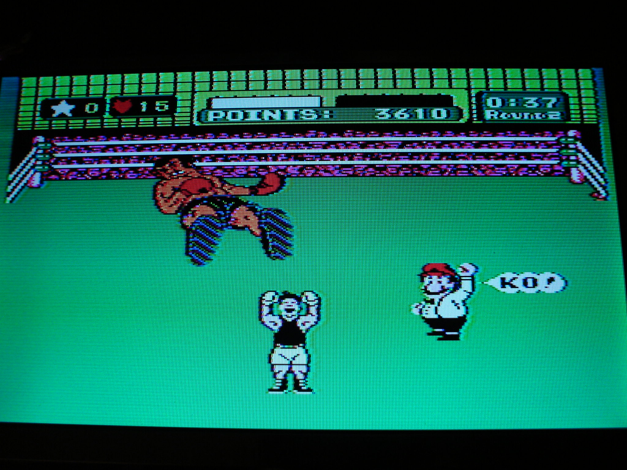
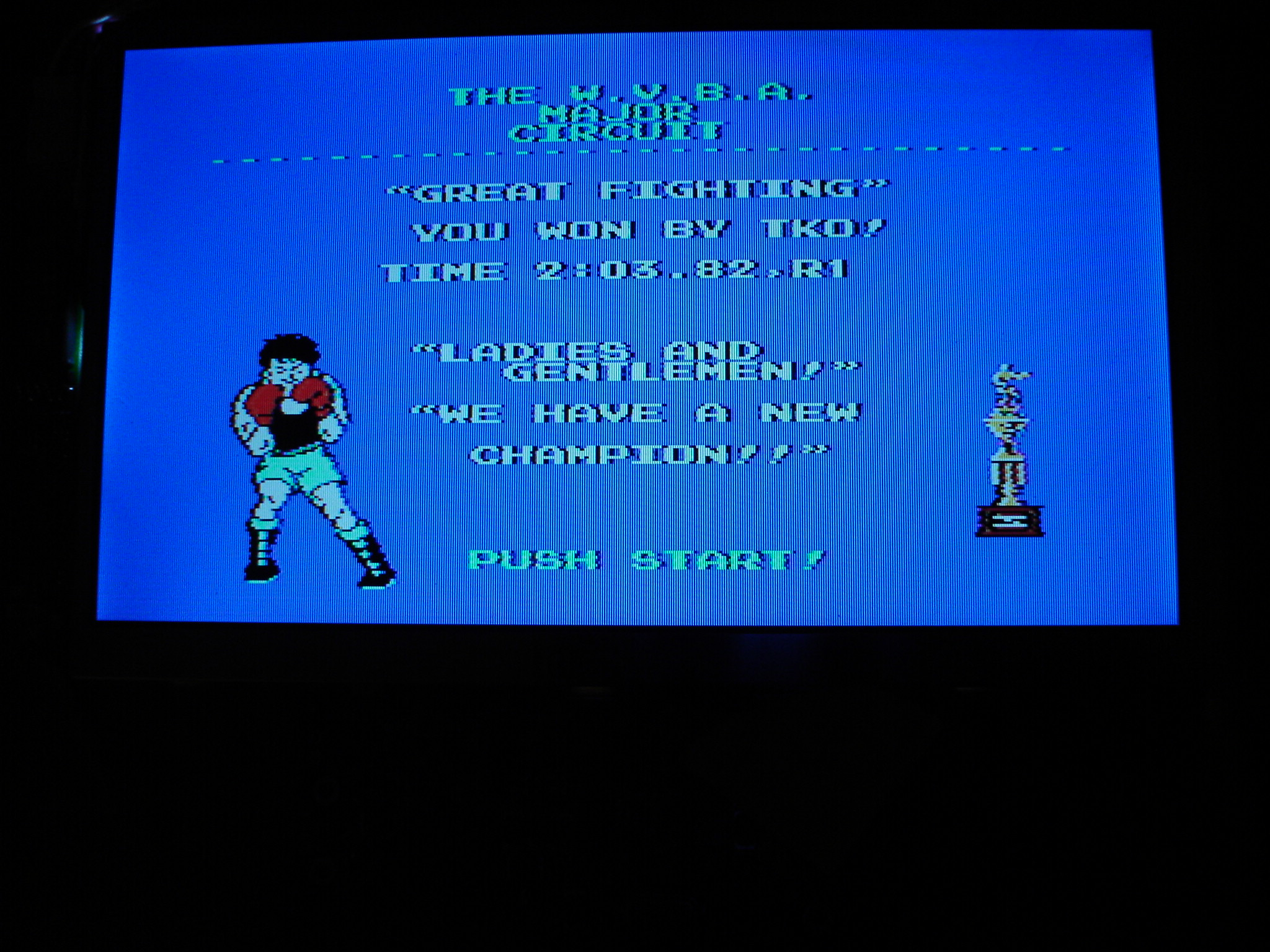
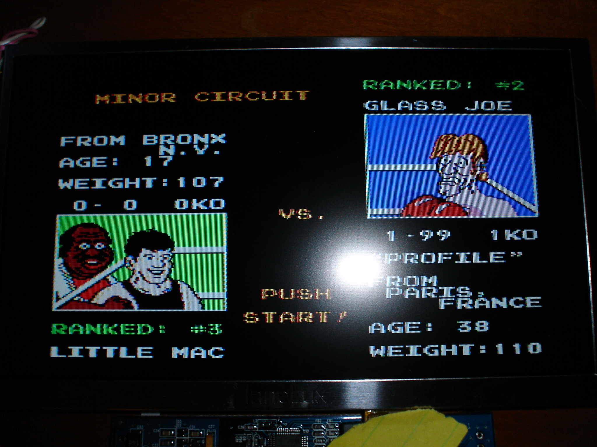
Here's some pics of the screen in action. In all 3 you can see it showing scenes from the single greatest boxing game ever, Mike Tyson's Punch Out!
<img src=http://www.austinbull.com/pictures/mtpo1.jpg width=400>
<img src=http://www.austinbull.com/pictures/mtpo2.jpg width=400>
<img src=http://www.austinbull.com/pictures/mtpo3.jpg width=400>
*EDIT*
Here's some pics of the screen in action. In all 3 you can see it showing scenes from the single greatest boxing game ever, Mike Tyson's Punch Out!
<img src=http://www.austinbull.com/pictures/mtpo1.jpg width=400>
<img src=http://www.austinbull.com/pictures/mtpo2.jpg width=400>
<img src=http://www.austinbull.com/pictures/mtpo3.jpg width=400>
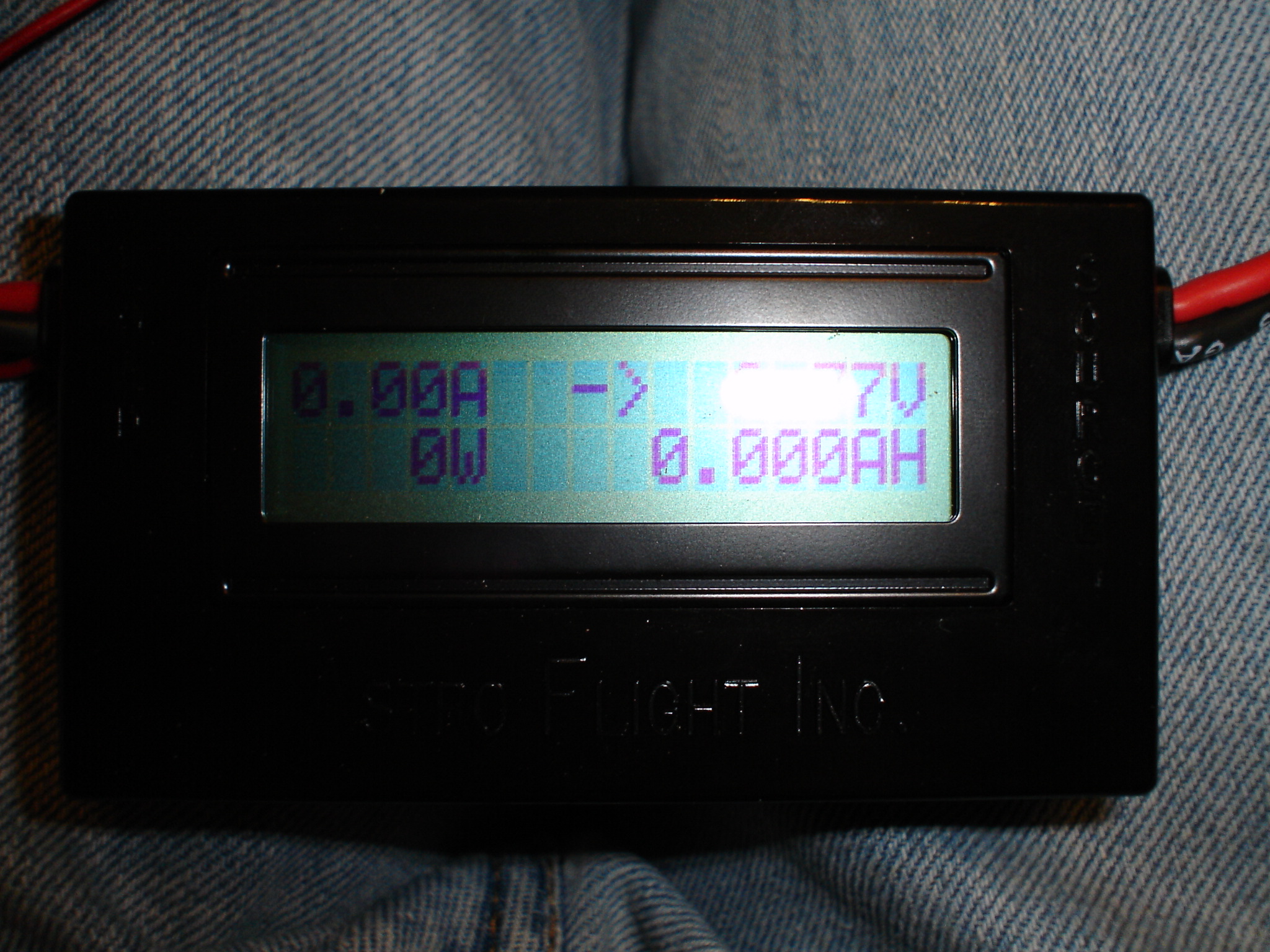
Well, I did some more testing on the screen to see what kind of current it draws, and it is suprisingly low for not having the LED mod done. To check current draw, I used a Astro Flight Super Whatt Meter. I bought it back when I started flying electric R/C airplanes to help when trying to decide on motor/prop combinations. A pic of it is below. Anyway, without the LED mod the screen pulls about 480 milliamps. With the LED mod it would be less, but why risk breaking a perfectly good screen just to squeeze a few extra minutes of battery life.
<img src=http://www.austinbull.com/pictures/wattmeter.jpg width=400>
As you can see in the picture, the meter shows how much voltage is coming in, how many milliamp hours you've used, the number of watts being generated, and the amps that the load is pulling. In the picture, all the numbers are 0 since I don't have a load connected. I also tested the unmodded Pelican Gameglass that I bought a while ago and it pulled just a shade over 500 milliamps. Needless to say, it won't be getting LED's either.
-
hcmtnbiker
- Posts:47
- Joined:Tue Nov 21, 2006 9:13 pm

I have a 7" DVD player, same layout (with the CCFL transformer on the left) and it is an innolux tft. But the encoder chip is unfortunately not the Sharp RB5P006AM. This chip has 25 pins on each of its 4 sides and has a big T on it. Other markings are "T100" "F23547.1" and "2705-VSDA2".
I wonder if anyone has any advice on where to start looking for information on this encoder, since "T" is such a generic piece of information. (I have searched google for the other bits of information). If I cannot find any information on this encoder, does anyone think it is possible to buy the encoder board from a different DVD player (one that uses the Sharp RB5P006AM) and hook that up to this TFT?
I wonder if anyone has any advice on where to start looking for information on this encoder, since "T" is such a generic piece of information. (I have searched google for the other bits of information). If I cannot find any information on this encoder, does anyone think it is possible to buy the encoder board from a different DVD player (one that uses the Sharp RB5P006AM) and hook that up to this TFT?