General electronics knowledge questions...

Want to just shoot the breeze? Forum 42 is the place!

Moderator:Moderators

Post Reply
User avatar
omfgcaps
Posts:30
Joined:Tue Jul 13, 2010 10:39 am
General electronics knowledge questions...

Post by omfgcaps » Wed Aug 11, 2010 9:55 pm

sorry if these questions aren't very educated..

1. What is vcc and how is it different from +V?

2. Whats the difference between -v and GND, and what are some examples of situations where you would use one or the other?

3. How can you determine which lines are data, which are voltage, and which lines do nothing? is there a special type of multimeter? for instance, someone figured out which lines on the DMG LCD are data, data, vsync and hsync.

4. How are data lines labeled? how does the label relate to functionality or w/e?

Image

please answer any or all of these questions, your help is appreciated

User avatar
mako321
Posts:711
Joined:Mon Aug 10, 2009 6:27 am

Re: General electronics knowledge questions...

Post by mako321 » Wed Aug 11, 2010 10:41 pm

http://en.wikipedia.org/wiki/IC_power_supply_pin" onclick="window.open(this.href);return false;
It's in there.

tom61
Senior Member
Posts:1517
Joined:Fri Mar 25, 2005 6:51 pm

Re: General electronics knowledge questions...

Post by tom61 » Thu Aug 12, 2010 12:55 pm

1) Basically the same
2) Complicated subject. For the purposes of most electronics that'd end up in a portable, consider them to basically mean the same thing.
3)An oscilloscope or multi-channel digital logic probe while the machine is running, or find a datasheet for the chips inside and work from its pinout to use a standard multimeter to check from the pins of the chip to various connector places.
4)Multiple standards exist for this.

User avatar
timmeh87
Senior Member
Posts:3047
Joined:Mon Nov 14, 2005 10:19 pm
Location:Ontario, Canada

Re: General electronics knowledge questions...

Post by timmeh87 » Thu Aug 12, 2010 6:47 pm

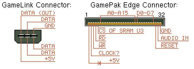
for #4, the pins are all just labeled with the name of the node, usually taken from a schematic. When talking about (and making) schematics, 'node' means any continuous line on the schematic (or metal conductor in reality). So nodes can each be named anything, If you are solving stuff with circuit equations you might just call them x and y, or v1 and v2. Usually any nodes hooked up to an integrated circuit will take on the name of the pin that they are connected to. All integrated circuits have names for all of their pins, given in the datasheet.

The point is, the labels on the pins in that diagram are specific to the integrated circuits that they are attached to. In the second image, I see a chip select (CS), read (RD) and write (WR) lines, which makes sense because it says its connected to some SRAM, and all SRAM chips have those pins. All the answers are in the datasheet specific to your integrated circuits.

I hope thats not confusing

Also, logic timing diagrams like this, taken from an n64 cart bus, help people understand how the signals relate to each other. This is similar to the output you would get from a logic analyzer.
http://crazynation.org/N64/n64_cart_info.htm" onclick="window.open(this.href);return false;
Image

"Linux is only free if your time is worthless"

Post Reply