Interact PSone Mobile Monitor Problem(s)

If you're making a portable you probably need something to watch it on. (Unless you want to guess what's happening in the game, but I wouldn't advise that) Anyway, this forum is your "Hacking a pocket TV/screen" one-stop solution. Share your experiences and knowledge here.

Moderator:Moderators

Post Reply
FyberOptic
Posts:3
Joined:Wed Oct 15, 2008 9:55 pm
Interact PSone Mobile Monitor Problem(s)

Post by FyberOptic » Sun Oct 26, 2008 9:44 pm

Hi folks, I found me one of these 4" Interact Mobile Monitor things for the PSone, with the PSone attached, for a whopping 99 cents. I expected it all to be dead, but as it turned out, it was just the monitor. That's unfortunate, cause I was actually buying it for the monitor rather than the Playstation! But I was wondering if anyone could shed some light on possible solutions to get this thing working.

First of all, I just want to confirm what AC adapter these things are supposed to use. From what I've heard, it uses the standard PSone adapter. I don't even have one of those, but I did have a 7.5v 2100ma adapter for an old USB hub. I found a connector that would fit into the PSone and switched it with the one on the AC adapter, and was good to go. That's how I found that the PSone worked, and the LCD apparently didn't. Hopefully I'm not feeding it too many amps, though.

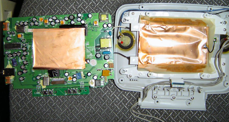
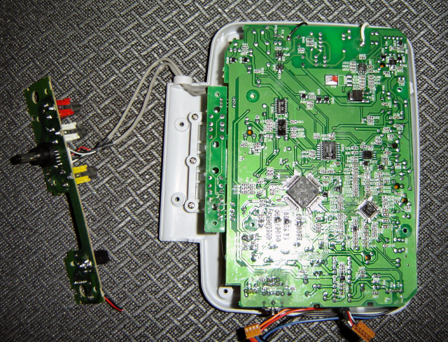
Next, I found that the pole in the power jack on the screen was broken. It took a bit of poking around to figure out why I wasn't getting any power at all, until I finally noticed the solder completely separated from the power/input board. This made sense, because the PSone wouldn't power on at all when the AC adapter was plugged into the screen instead of directly onto the console. After opening it, I found that the power should pass directly through to the console, but wasn't happening due to the trace being split in half from the break.

So, I cut the power connector cable that goes to the screen's PCB and wired the AC adapter straight to that. Even that didn't turn out as easy as I thought, because the wires are apparently the wrong color. The black wire leads into the power circuitry, while the red wire apparently goes right to the ground connections.

Once wired the right way, I did some basic testing with the multimeter. Power is certainly being fed into the 7805 regulator, and 5v is definitely coming out. From there I really have no idea what's wrong.

Does anyone know of any little fuses or anything that might be hidden on there and causing the problem? I perused the board but don't think I saw any from first glance. I also tested the power button itself to make sure it was still working, then the connectivity of the connection up to where it leads (a pin on the square chip that's rotated 45 degrees).

Even if the board is fried, the LCD could be promising. It's a Toshiba TFD40W11-B. Unfortunately I can't find a datasheet anywhere. But I did find this:

1[in] logic power (5V)
2[in] horiz sync input
3[in] vert sync input
4[out] signal voltage / phase inversion control out
5[in] ground Vss (0V)
6[in] R video
7[in] G video
8[in] B video
9[in] common voltage input
10[in] Vbb (13V)
11[in] Vgg (25V)
12[out] common voltage / phase inversion control output
13[in] Vss (0V)
14[in] NTSC/PAL selection
15 NC
16 NC

Apparently it's capable of directly accepting RGB and sync signals. But I have to admit that wiring one up to something without something to go by is a bit out of my league. Mostly for the pins like Vbb, Vgg, etc. I'm assuming that backlight is CCFL, which would also take a bit of effort to get going, since I think they need an inverter to get 100v or something.

Anyway, any help anyone can provide would be much appreciated. If nothing else, maybe somebody will find some use from the pinout and/or pictures. Thanks in advance!
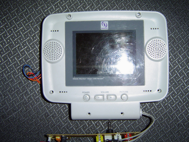
Image

Image

Image

tom61
Senior Member
Posts:1517
Joined:Fri Mar 25, 2005 6:51 pm

Post by tom61 » Mon Oct 27, 2008 5:30 pm

You can't fry something by providing it more amps, devices take only what they need to run.

By wiring it in backwards (never trust color codes), you probably fried a few things on the board. Finding blown microfuses is pain.

That is a very odd pinout for a bare LCD. VBB or VGG is likely the voltage to drive the CCFL.

FyberOptic
Posts:3
Joined:Wed Oct 15, 2008 9:55 pm

Post by FyberOptic » Tue Oct 28, 2008 1:11 am

tom61 wrote:You can't fry something by providing it more amps, devices take only what they need to run.
I mostly meant in terms of an unregulated AC adapter. If I understand correctly, the voltage ratings on them are directly related to the amount of rated amps also being used. Otherwise, going by ohms law, using a different amount of amps than what's rated would result in a different amount of volts from the AC adapter, I believe. If so, my concern was using an AC adapter with more amps than what the device should use would feed it too many volts. A regulated AC adapter though would put out a steady voltage regardless of amps used. Feel free to correct me if I'm not correct on any part of that though.

tom61 wrote: By wiring it in backwards (never trust color codes), you probably fried a few things on the board. Finding blown microfuses is pain.
Going by the condition it was in when I got it, I would bet that it was already dead. But I do hate that I hooked it up backwards initially, cause now I'll never know. At least I know better than to trust the colors from now on.

tom61 wrote: That is a very odd pinout for a bare LCD. VBB or VGG is likely the voltage to drive the CCFL.
I dunno, as you can see in the one picture, there appears to be some circuitry in place already for stepping it up to run the backlight. That thick black and white wire between the lcd area and the circuit board is the backlight power connection. There's also a ground wire between the metal casing of the LCD and the metal foil covering behind the backlight. Not exactly made for easy disassembly. But I've never looked in an official PSone LCD to see if they're much different.

When I was perusing the board near the LCD's ribbon cable, I noticed that it appeared that some of the pins didn't go anywhere. Checking again just now, I don't see a trace coming from 4, 5, 9, 13, 15, 16. If that pinout above is correct, and I honestly have no way to confirm it, then none of the grounds would be connected. At least on the ribbon. As I mentioned, the LCD shielding is in fact grounded to the rest of the unit by a black wire, so maybe they didn't need the grounds connected in the ribbon. I dunno.

Anyhoo, I'll keep poking around with it in case I might get lucky and find the problem, but I'll also see about researching similar screens to see if I can find a datasheet that might help me figure out how to use just the LCD. I could use LEDs for a backlight instead of that CCFL mess. If I have any luck, I'll post back here.

Of course, if anyone else has any experience driving these or similar panels directly, I'd love to hear it!

User avatar
GeckoLink
Posts:111
Joined:Sat Jul 03, 2010 11:56 am

Re: Interact PSone Mobile Monitor Problem(s)

Post by GeckoLink » Sat Jul 03, 2010 4:30 pm

can you give me the pinout of the ps1 video connecter
Image

Post Reply