Just looking at some stuff to build my own gcp. Probably work on it over winter break. Here's what I'm thinking of buying.
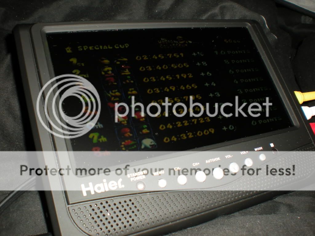
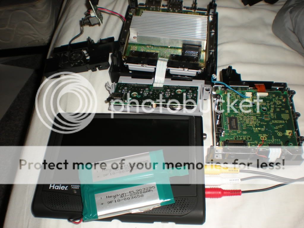
Haier 7" LCD Portable TV (has composite in, as a plus can take the over-the-air digital TV. Batteries supposedly last 2.5hr). Not sure on the specs on the batteries.
Gamecube and controller (of course...)
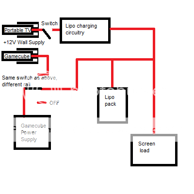
Using the specs from zenloc's post, I plan on building my own power supply (I have previous experience making power supplies.)
Depending on the batteries from the portable TV, I plan on either using those or buying my own.
Not sure on the case, probably just a couple sheets of acrylic for starters.
EDIT: found the replacement batteries on amazon: 7.4V 2200mAh. Not horrible, but still
EDIT: Some Math:
The built-in batteries:
7.4*2.2 = 16.28 W h
The gamecube, from the link above, doing some math:
1.9*6.6+3.3*.8+5.0*.3+12*.05 = 16.14 W power draw
The screen:
16.28 W h / 2.5h = 6.512 W
So a total of ~ 23 W of power draw
16.28 Wh / 23W = .7hr, so if you had a nominal power supply (100% efficiency), you would be able to get ~42-45 minutes. Since ~80% efficiency tends to be achievable, 33-36 minutes would be a reasonable amount to expect.
So I will probably be buying some better batteries. If I wanted >2hr, I would need almost 60 Wh of battery power, so 7800 mAh @ 7.4V or 5200 mAh @ 11.1V
(If you want help with the math, WattHours = (<desired time> / .
(Once you have WattHours, divide it by the battery voltage to determine the amount of mAh you need )