LED in Cart
Moderator:Moderators
I was just wondering, (after I just reemed the screws in a SNES cart out) what i could do with it. I was considering putting an LED on the cart so when it is inserted and the SNES is powered on, the LED on the cart will light, my only problem is, is that i dont know where to solder it, and wheather or not it will mess with the game while it is playing. Other then that i am fine.

I found a site (http://pinouts.ru/data/CartridgeSnes_pinout.shtml) it goes up to 58, yet there are only 47 pins on the SNES cart, correct me if im missing something, im new at cartrige boards
EDIT: I think I understand now, the only problem i am facing now is where do i put the LED
EDIT: I think I understand now, the only problem i am facing now is where do i put the LED
-
xriverfalconx

- Posts:481
- Joined:Tue Jul 19, 2005 12:57 pm
- Location:Vana'Diel - Titan Server
- Contact:
Pin 27 and 58 i see gives the +5 V for ya...as for the other pins with nothing in them...theoretically speaking, if those pins were removed from the cart slot, does anyone think that the snes would run the game still???
If it DOES work, then removing the cart slot and adding wires just got a WHOLE lot easier!!! I have an extra SNES (original) that I could test this on. However, I would rather get some opinions on this first before trying it out.
If it DOES work, then removing the cart slot and adding wires just got a WHOLE lot easier!!! I have an extra SNES (original) that I could test this on. However, I would rather get some opinions on this first before trying it out.
-
Cyberblade

- Posts:154
- Joined:Mon Jun 28, 2004 11:18 am
You could re-wire it without those pins, but games such as Starfox and specialty chip games won't run. Look on the bottom of SNES carts, some have the full amount of pins, others don't.xriverfalconx wrote:Pin 27 and 58 i see gives the +5 V for ya...as for the other pins with nothing in them...theoretically speaking, if those pins were removed from the cart slot, does anyone think that the snes would run the game still???
If it DOES work, then removing the cart slot and adding wires just got a WHOLE lot easier!!! I have an extra SNES (original) that I could test this on. However, I would rather get some opinions on this first before trying it out.
-
xriverfalconx
- Posts:481
- Joined:Tue Jul 19, 2005 12:57 pm
- Location:Vana'Diel - Titan Server
- Contact:
Seems like a lot of effort to put an LED in every cart. I'd say your biggest problem might be if too much current goes through the LED, but you can probably solve this with the right sized resistor. As stated above, watch out for just touching the LED to random pins. In the electronics world, that's generally a straight road to badness. It sounds like you've got it worked out though. I'd recommend maybe looking for a way to keep the LED in the system itself though, just because that seems easier.


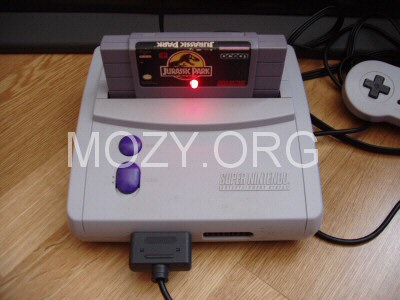
Like this?
Done.
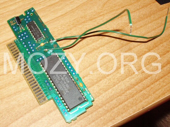
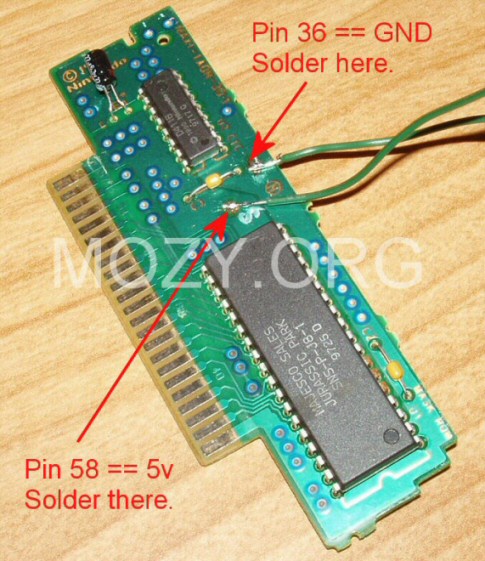
Check "SNES Kart" dox for pinouts. Great document. Pin 58 is +5V and Pin 36 is +0v (GND). Other side has the same stuff..diff pins.
I stripped off the PCB coating layer on the PCB where pins 58 and 36 have long connection strips as you can see. Tested with multimeter to make sure I got the right place.
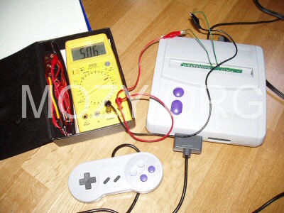
DMM test to make sure I actually got everything right. Pretty constant 5.05/5.06v so everything's great.
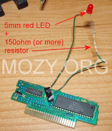
Soldered a 5mm LED and 150ohm resistor to the wires. 150ohm is probably too small (too much current to LED) but I don't care. This was just a test and I'll never actually use this cart (the game sucks ass).
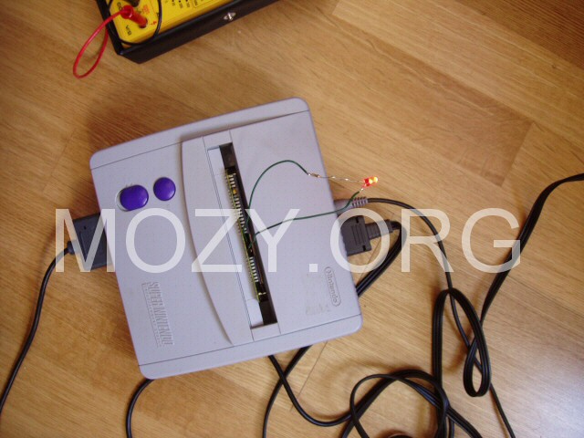
Another test this time to make sure the LED lights. It does.
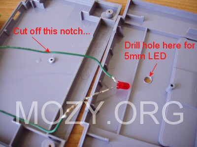
Inside the cart. Had to cut off that notch so it wouldn't hit my badly-placed LED cabling. Oh and drilled a hole for the LED. Great place to put it cause the cart actually had a notch there that was like an indentation or something... Would have been a good idea if I covered the leads and prevented them from shorting out stuff, but the placement is pretty great and I really don't care enough.
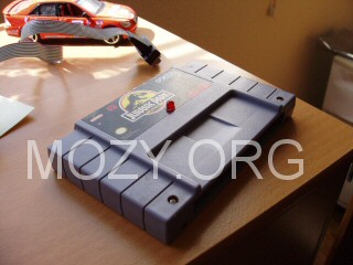
Final shot of the completed cart. Nice eh? Heh.
Done.
Check "SNES Kart" dox for pinouts. Great document. Pin 58 is +5V and Pin 36 is +0v (GND). Other side has the same stuff..diff pins.
I stripped off the PCB coating layer on the PCB where pins 58 and 36 have long connection strips as you can see. Tested with multimeter to make sure I got the right place.
DMM test to make sure I actually got everything right. Pretty constant 5.05/5.06v so everything's great.
Soldered a 5mm LED and 150ohm resistor to the wires. 150ohm is probably too small (too much current to LED) but I don't care. This was just a test and I'll never actually use this cart (the game sucks ass).
Another test this time to make sure the LED lights. It does.
Inside the cart. Had to cut off that notch so it wouldn't hit my badly-placed LED cabling. Oh and drilled a hole for the LED. Great place to put it cause the cart actually had a notch there that was like an indentation or something... Would have been a good idea if I covered the leads and prevented them from shorting out stuff, but the placement is pretty great and I really don't care enough.
Final shot of the completed cart. Nice eh? Heh.