Has anyone ever made (and released) a N64 schematic (either full or partial)? I know kibble did some PCB re-engineering (although he went dead again), and I have read the posts made by Ozone and stuntpenguin007
Ozone: http://forums.benheck.com/viewtopic.php ... 7&start=15" onclick="window.open(this.href);return false;
Penguin: http://forums.benheck.com/viewtopic.php?f=5&t=38916" onclick="window.open(this.href);return false;
However, did anyone finish it / post a part of it? I'd really want to have a try at making a PCB. Anyways, if there is no other I already started to draw a schematic, although I'd prefer to use someone else's if the community has one. If anyone has a full schematic, please tell me so. If it is partial, at least it helps me do a sanity check.
Edit: does anyone know what U8 is on a NUS-CPU-03 board? It is a sot-23-5 marked only as 2876. My Google-fu isn't strong today.
Dunno why I had the idea it was U8, U3. U8 was identified by kibble in his t64 resurrection post.
Nintendo 64 Schematic
Moderator:Moderators
Last edited by genious 7 on Sun Jul 22, 2012 8:53 am, edited 1 time in total.
Re: Nintendo 64 Schematic
If any mod sees this, delete this thread. After I edited the post above, the whole thread dissapeared from the forum (probably since the first post´s edit was waiting for approval) and I created another one without thinking why it disapeared. Id like to focus anything on the other thread.
edit: NVM, this one seems more popular, lock the other one. It would be helpful to state on the "your post waiting for approval" (its my first posts here), that if you edit the first post without any reply, the whole thread dissapears.
edit: NVM, this one seems more popular, lock the other one. It would be helpful to state on the "your post waiting for approval" (its my first posts here), that if you edit the first post without any reply, the whole thread dissapears.
Last edited by genious 7 on Sun Jul 22, 2012 9:09 am, edited 1 time in total.
-
evilteddy

- Portablizer
- Posts:423
- Joined:Tue Mar 25, 2008 2:11 am
- 360 GamerTag:Kirren of Smeg
- Steam ID:kizzinator
- Location:Newcastle, Australia
Re: Nintendo 64 Schematic
If I remember correctly its a quadruple tristate buffer for the controller ports. Don't take that as gospel though because google suggests its a 4 way multiplexer. :p
-
jjhammerstein

- Senior Member
- Posts:1562
- Joined:Tue Nov 18, 2008 7:15 pm
- Location:Southern CT
- Contact:
Re: Nintendo 64 Schematic
You can remove the U8, little known fact.
Here it is working without it, recognizing a controller:
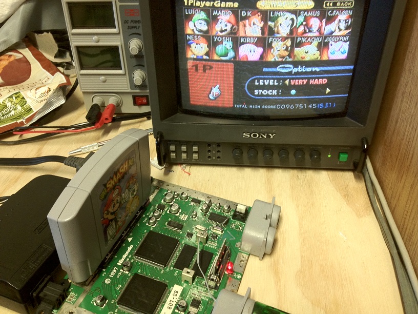
Connect P1 Data to both pins 15 and 16 on the PIF chip, it works just fine.

Ignore those other wires, they are for RCP wiring.
Here it is working without it, recognizing a controller:
Connect P1 Data to both pins 15 and 16 on the PIF chip, it works just fine.
Ignore those other wires, they are for RCP wiring.
GET FREE WOW GOLD SEX VISIT MODRETRO
Re: Nintendo 64 Schematic
Sorry, got the ic number mixed up. U8 is for the player controls. Its U3 what I'm struggling with. Its a sot-23-5, pins 1-3 to ground, pin 5 to +3.3v, and pin 4 to pin 8 of the Pif-nus.
What I have made already:
https://picasaweb.google.com/lh/photo/Q ... directlink" onclick="window.open(this.href);return false;
Yea, I know its really messy, but whatever. Ill be cleaning it during the week.
Hey, jjhammerstein, your u3 has a different code than mine (probably the last number is a batch number.) what does yours read (right above the Pif-nus) I think I can kinda read a 28hl
-
jjhammerstein
- Senior Member
- Posts:1562
- Joined:Tue Nov 18, 2008 7:15 pm
- Location:Southern CT
- Contact:
Re: Nintendo 64 Schematic
I am pretty sure you can just bridge over that, just connect the two pins that aren't ground. Try it, but I think I remember doing that.
GET FREE WOW GOLD SEX VISIT MODRETRO