Do we have room for another N64P? (t64 WIP)
Moderator:Moderators
-
runkillerrabbit
- Posts:32
- Joined:Sun Sep 27, 2009 3:10 am
hehe can i ask how did you learn to use all the micro controllers?
-
stuntpenguin007

- Posts:667
- Joined:Sun Apr 27, 2008 12:21 pm
Re: Do we have room for another N64P? (t64 WIP)
what exactly are you referring to when you say "micro controllers"? I'm sure the original thumb stick could be used with a pic microcontroller to convert it to a digital thumbstick... sort of.runkillerrabbit wrote:hehe can i ask how did you learn to use all the micro controllers?
How exactly do you plan on doing this kibble? If you are planning on using a pic, you can basically say open or closed, so there's no in between. The only way I could think of to connect it to the controller would be by putting a semiconductor across gnd and one of the potentiometer contacts, then you'd have to run voltage into the controller's microcontroller thing, which could possibly damage it.
@runkillerrabbit I'm not very good at pic programming, but here's where I started to learn http://www.mstracey.btinternet.co.uk/pi ... icmain.htm" onclick="window.open(this.href);return false;
SNESP WIP
Case - 50%
acquired parts - 90%
assembly - 0%
Case - 50%
acquired parts - 90%
assembly - 0%

Re: Do we have room for another N64P? (t64 WIP)
Ho ho! No, I don't know how to use "all" the microcontrollers, I've actually just recently learned how to make them flash LED's on and off and take inputs from switches to make them do different things. I got some real basic learning kits and have been messing with the sample code and made a few of my own.runkillerrabbit wrote:hehe can i ask how did you learn to use all the micro controllers?
The way I thought about doing it is this: Make one of the ports on a particular PIC micro analog input, have the two potetiometers (x and y axis) each going into one of the A/D inputs of the PIC. Have the microcontroller frequently read the value and store it. If the value is the same, have it not do anything. If the value changes either up or down, the micro compares the original value to the new value and determines if the change was positive or negative. If it's positive, have it output the quadrature signal that the original analog stick would output and apply it to the input from the original controller chip. If it's negative, then the opposite would happen. At the same time, the micro would have to keep track of how much up or down the value has changed to prevent erratic operation of the control stick, so technically, the total up/down, left/right movements could be adjusted to a certain range with software. It's a bit more complicated than this, but this is the basic of how it would work.stuntpenguin007 wrote:How exactly do you plan on doing this kibble? If you are planning on using a pic, you can basically say open or closed, so there's no in between. The only way I could think of to connect it to the controller would be by putting a semiconductor across gnd and one of the potentiometer contacts, then you'd have to run voltage into the controller's microcontroller thing, which could possibly damage it.
In other news, I'm still working on the board design. I've begun collecting parts for the audio section. I have these tiny speakers I'm gonna use, smaller than the PSone screen speakers and 1.5W @ 4 ohm. They will be driven by a pair of 3W amps. I'll post up some pics later on. I've been having to delay ordering the screen and other parts for a while now. Just when I think I'll have enough money, something happens, plus it doesn't help they've been cutting down hours at work.
This is taking forever, I know....
Coming Soon: Kibble's L'Ectroshop (parts and stuff FS)
Re: Do we have room for another N64P? (t64 WIP)
OMG pics!!! 
Thought I would add some new stuff to this thread to hopefully keep you guys content for a while.
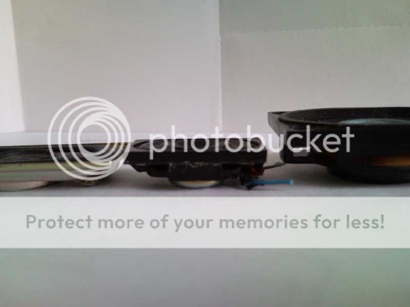
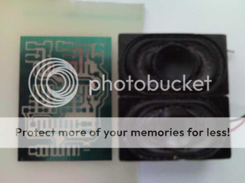
So, let me start off by showing you the speakers I'm gonna use. Two pics; one shows the size of them compared to a PSOne speaker and two others I had considered using when I first started this project. The one on the left is the PSOne speaker, the one to the right of the PSOne speaker is the first type I had considered using. The second one from the right is the second type I considered using, much thinner, but otherwise the same as the previous. The one to the right is the one's I'm gonna use. The second pic shows how thick they are compared to a PSOne speaker and the thinnest one I was gonna use before these.

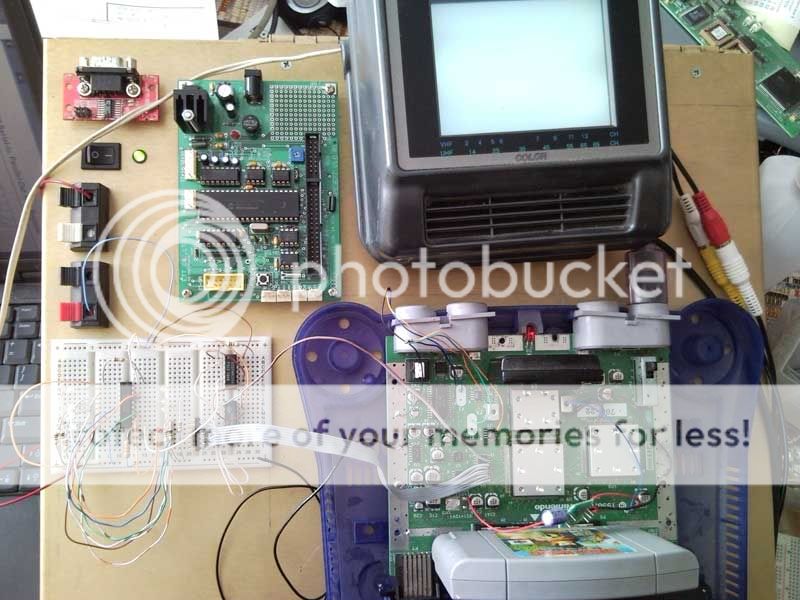
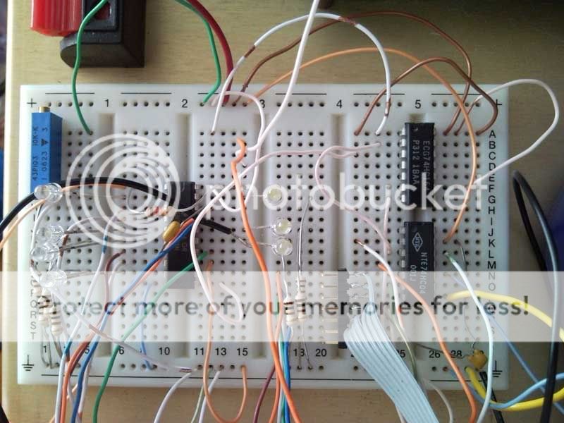
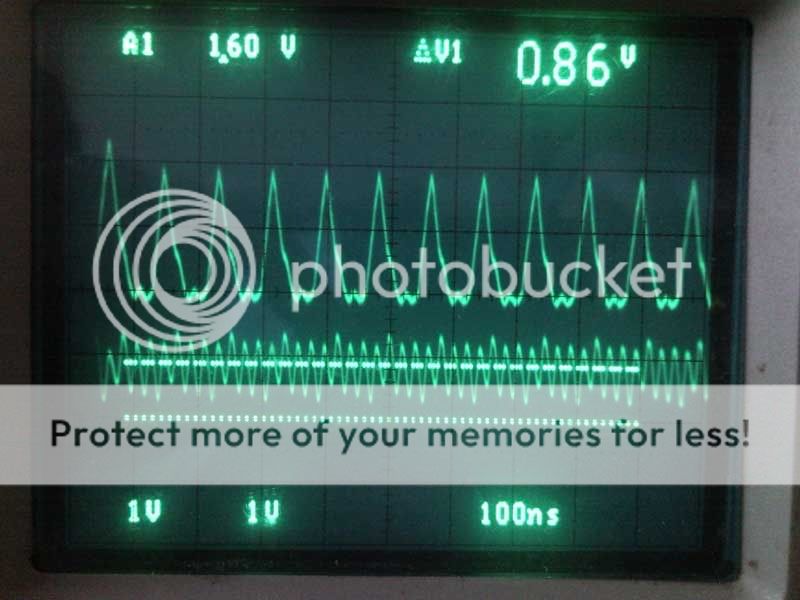
The following pics are of a test setup I've been messing with to try to de-multiplex the color info from the RCP's output, since I don't have a programmed chip to do this for me, I am trying to attempt to get it to work with discrete IC's and some LED's to visualize what's going on. This is only one of the 4 required demux's. Unfortunately, it doesn't work properly because of voltage related reasons from the clock sources. the 4 pics of the scope show what's going on.
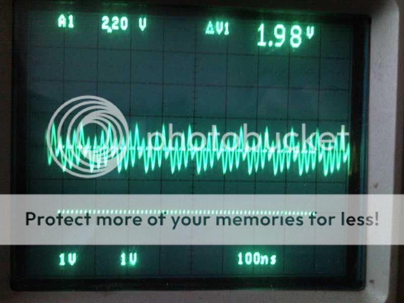
This is the clock going from the MX8330 chip to the RCP and ADC. The bottom dashed line is the gnd reference and the top dashed line is the difference between the two. As you can see, the max voltage it's reaching is 2.20V and 1.98V is about the middle point between high and low.
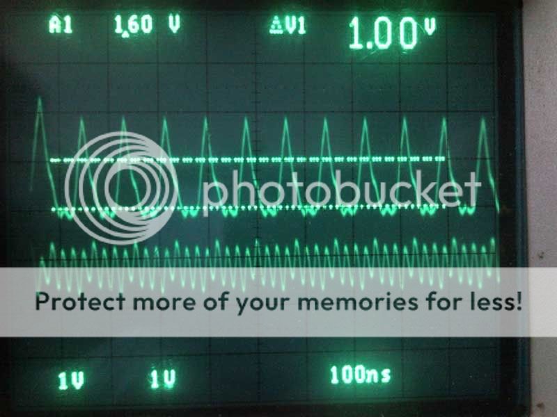
This is the clock output from RCP to DAC. The voltage reaches up to 2.80V and has a halfway point of about 2.20V between high and low.

These pics show the output from an 74HC04 inverter. As you can see, the signals are inverted ok, but the output voltages are way lower than the input, which sucks because with outputs that low going into it's inputs, the shift register doesn't operate.
I'm thinking using some high speed comparators at the clock inputs to help bring the voltages up to more acceptable levels.
Thought I would add some new stuff to this thread to hopefully keep you guys content for a while.
So, let me start off by showing you the speakers I'm gonna use. Two pics; one shows the size of them compared to a PSOne speaker and two others I had considered using when I first started this project. The one on the left is the PSOne speaker, the one to the right of the PSOne speaker is the first type I had considered using. The second one from the right is the second type I considered using, much thinner, but otherwise the same as the previous. The one to the right is the one's I'm gonna use. The second pic shows how thick they are compared to a PSOne speaker and the thinnest one I was gonna use before these.
The following pics are of a test setup I've been messing with to try to de-multiplex the color info from the RCP's output, since I don't have a programmed chip to do this for me, I am trying to attempt to get it to work with discrete IC's and some LED's to visualize what's going on. This is only one of the 4 required demux's. Unfortunately, it doesn't work properly because of voltage related reasons from the clock sources. the 4 pics of the scope show what's going on.
This is the clock going from the MX8330 chip to the RCP and ADC. The bottom dashed line is the gnd reference and the top dashed line is the difference between the two. As you can see, the max voltage it's reaching is 2.20V and 1.98V is about the middle point between high and low.
This is the clock output from RCP to DAC. The voltage reaches up to 2.80V and has a halfway point of about 2.20V between high and low.
These pics show the output from an 74HC04 inverter. As you can see, the signals are inverted ok, but the output voltages are way lower than the input, which sucks because with outputs that low going into it's inputs, the shift register doesn't operate.
I'm thinking using some high speed comparators at the clock inputs to help bring the voltages up to more acceptable levels.
Coming Soon: Kibble's L'Ectroshop (parts and stuff FS)
Re: Do we have room for another N64P? (t64 WIP)
What's the part # for the ones you're using? I'd love to use some smaller speakers for my next project.

Re: Do we have room for another N64P? (t64 WIP)
They have 2514k1m1-1 on the back of them, but I got them out of an hp laptop. The part number for the assembly is: 417089-001. You can find a bunch of them on ebay for pretty cheap.
Coming Soon: Kibble's L'Ectroshop (parts and stuff FS)
Re: Do we have room for another N64P? (t64 WIP)
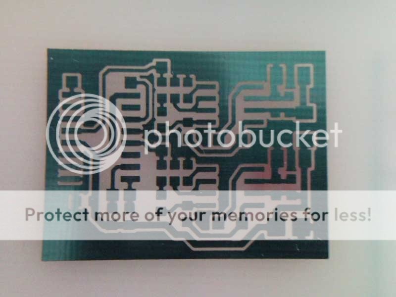
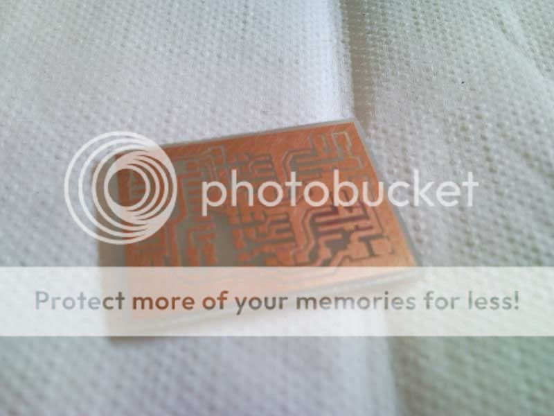
Made the circuit board for the audio amp. It's gonna have two LM4871 amps and a DS1803-010 digital pot for volume adjustment which will be controlled through I2C. The whole board is just about the size of both speakers side by side. I applied a red glass paint to the board to work as a solder mask. I have to let it dry overnight and then bake it tomorrow. After that, I'll solder the components to the board.

Coming Soon: Kibble's L'Ectroshop (parts and stuff FS)
-
andrewdorsey

- Posts:183
- Joined:Mon Dec 01, 2008 2:49 pm
- Location:hmmmmmmm
Re: Do we have room for another N64P? (t64 WIP)
Would you consider making more of these little audio amps to sell???
Re: Do we have room for another N64P? (t64 WIP)
With or without digital pot? I can make the boards no problem, but I only have enough components to make another one without the pot. I'd have to see if I can order these parts. I just happened to have them around so I decided to use them.
Once I get it all assembled, I'll test it out with a PIC to make sure it works the way it should.
Once I get it all assembled, I'll test it out with a PIC to make sure it works the way it should.
Coming Soon: Kibble's L'Ectroshop (parts and stuff FS)
Re: Do we have room for another N64P? (t64 WIP)
Got the amp all assembled, I'll be trying to write some code for the PIC tonight, if I get back from class early enough, to see if I can get the PIC to write different values to the digital pot and control the volume.

Coming Soon: Kibble's L'Ectroshop (parts and stuff FS)

Re: Do we have room for another N64P? (t64 WIP)
looks awesome!(and red)

Re: Do we have room for another N64P? (t64 WIP)
Good work, I like. I really admire how you are etching your own boards.
-
andrewdorsey
- Posts:183
- Joined:Mon Dec 01, 2008 2:49 pm
- Location:hmmmmmmm
Re: Do we have room for another N64P? (t64 WIP)
With everything already installedkibble wrote:With or without digital pot? I can make the boards no problem, but I only have enough components to make another one without the pot. I'd have to see if I can order these parts. I just happened to have them around so I decided to use them.
Once I get it all assembled, I'll test it out with a PIC to make sure it works the way it should.
Re: Do we have room for another N64P? (t64 WIP)
If I can get everything working properly, I'll consider ordering the parts and making more.andrewdorsey wrote:With everything already installed
I got some code running on a PIC16F873 to control the potentiometers. It works except there's a bit of a problem where the sound is distorted and even when the volume is all the way low, you can still hear it a bit through the speakers.
Coming Soon: Kibble's L'Ectroshop (parts and stuff FS)
-
ShockSlayer

- Niblet 64
- Posts:5059
- Joined:Thu Jun 29, 2006 12:47 pm
- Location:In my inbox.
Re: Do we have room for another N64P? (t64 WIP)
Hmm...I guess I don't know too much into what's going on there, but judging by how quickly the screen gets distorted it sounds like your amp might not be getting enough power, or the right voltage or something. What you are doing is quite a bit past me so....yeah.
SS
SS
http://twitter.com/ShockSlayer" onclick="window.open(this.href);return false;