Includes but not limited to: SNES, Genesis, Sega CD, PlayStation 1, Nintendo 64, Dreamcast, Game Gear and I guess the Virtual Boy.
Moderator:Moderators
-
Designer noob
- Posts:171
- Joined:Tue Apr 14, 2009 12:12 am
Problem and Question
Post
by Designer noob » Sat Jun 20, 2009 7:20 pm
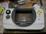
I opened my battery today and I have two question about them. The red circles indicate where you solder a wire from there to the charger. I was wondering where are the spots that you solder to the screen? I was thinking the two blue circles were the spots. But, when I looked at Bacteria's screen diagram. There is only one pin to put the power in which is, Socket 1 pin 12.
Answered

Next, the problem. I opened my screen today and there was a capacitor glued to the lid and I riped it from the board. So, now I have a board that is trash unless I can find where the capacitor came from and solder it back on. My dad and I think we know where it came from, but we want a second opinion. The red area is the radius of which we think it came from and the two blue spots are where we think it came from exactly. If you guys know where the capacitor came from or have a quess don't be afraid to tell me. Thanks for the help. If you need any more information and pictures I will be glad to take some. This is a zenith screen.

Also, I was wondering if anyone could explain to me how to hook up a 2p2t switch, so that you can switch the lines between the first controller inserted into the portable and the other four ports.
AnsweredLast edited by
Designer noob on Sun Jun 21, 2009 10:30 pm, edited 4 times in total.
The N64/GBA Remix
 ............................................................................................................................................. Xbox360 WVI
-
gamerjr
- Posts:153
- Joined:Sat Mar 08, 2008 9:57 pm
-
Contact:
Post
by gamerjr » Sat Jun 20, 2009 9:21 pm
O.o thats a big ass compasistor for the PSOne screen. have you tried turning the screen on? the only one i could think of is uneeded if you run it off of batteries. and its not that big.
-
argelfraster
- Posts:984
- Joined:Sun Sep 07, 2008 3:14 pm
-
Contact:
Post
by argelfraster » Sat Jun 20, 2009 10:01 pm
gamerjr wrote:O.o thats a big ass compasistor for the PSOne screen. have you tried turning the screen on? the only one i could think of is uneeded if you run it off of batteries. and its not that big.
Did you mean
capacitor?
Btw, I have never had a psone screen with that kind of cap up there.
And if thats a gamecube screen, you dont even need that cap.
I ripped mine off and the screen still worked.
-
neverused
- Posts:290
- Joined:Fri Feb 06, 2009 6:14 pm
Post
by neverused » Sat Jun 20, 2009 10:20 pm
That screen looks like a zenith and I have the exact same screen. The two blue circles are correct, according to my screen.
-
Designer noob
- Posts:171
- Joined:Tue Apr 14, 2009 12:12 am
Post
by Designer noob » Sun Jun 21, 2009 3:35 pm
If any more knows the answer to the screen question you can go ahead and post it. I would like a little more confirmation on it. Also, if you guys know the anwser to the other questions I would be glad to hear them. thanks.
The N64/GBA Remix
............................................................................................................................................. Xbox360 WVI
-
timmeh87
- Senior Member
- Posts:3047
- Joined:Mon Nov 14, 2005 10:19 pm
- Location:Ontario, Canada
Post
by timmeh87 » Sun Jun 21, 2009 8:14 pm
Designer noob wrote:If any more knows the answer to the screen question you can go ahead and post it. I would like a little more confirmation on it. Also, if you guys know the anwser to the other questions I would be glad to hear them. thanks.
We just say "bump" and it basically means what you said.
Anyways that looks more like an inductor but its hard to tell from the small picture. (You could check by measuring its resistance). Whatever it is, it probably wasn't in the original design, because it was added to surface mount pads when it is a through-hole part. The screen might work fine without it is what I'm saying. My understanding is that Zenith screens are just re branded PSOne screens, and my screen does not have that part.
For the battery, in a lot of circuits you use the same terminals for both charging and discharging. If you want to charge the battery while using the system, your battery charger better be able to handle at least twice the current. If its a lithium battery it had better be a 'smart charger' rather than an unregulated power supply..
The terminals marked in blue appear to be the battery side of the protection circuit, taking power from there would completely bypass the protection.

"Linux is only free if your time is worthless"
-
Designer noob
- Posts:171
- Joined:Tue Apr 14, 2009 12:12 am
Post
by Designer noob » Sun Jun 21, 2009 9:02 pm
The terminals marked in blue appear to be the battery side of the protection circuit, taking power from there would completely bypass the protection.
I check with a ohmmeter and both the blue and red give off 8.4 volts. So, I quess there are two terminals. What do you mean by if I took energy I would bypass the protection of the circuit. Even if I did bypass the protection circuit it won't matter. The protection circuit makes sure the battery wont over charge. I will be useing that terminal for powering the screen and the red ones for charging.
The N64/GBA Remix
............................................................................................................................................. Xbox360 WVI
-
Designer noob
- Posts:171
- Joined:Tue Apr 14, 2009 12:12 am
Post
by Designer noob » Mon Jun 22, 2009 4:32 pm
I have a question about how to wire the screen. I am just making sure I am correct. The area is red should be cut and the socket in area blue should be pulled out. If this is true, then what happens to the wires in the purple area? They are glued to certain areas, so I am quessing they must have to be reconnected to something.

The N64/GBA Remix
............................................................................................................................................. Xbox360 WVI
-
neverused
- Posts:290
- Joined:Fri Feb 06, 2009 6:14 pm
Post
by neverused » Mon Jun 22, 2009 10:31 pm
You can desolder all of the extra wires, including the thick black wire, thicker red wire, and the large cap too. After that, just use the stickies to hook the screen up to your 64.
-
Designer noob
- Posts:171
- Joined:Tue Apr 14, 2009 12:12 am
Post
by Designer noob » Tue Jun 23, 2009 12:14 am
kk thanks for the help. I plan on wiring the whole system up tomorrow (exepct for the controller).
The N64/GBA Remix
............................................................................................................................................. Xbox360 WVI
-
Designer noob
- Posts:171
- Joined:Tue Apr 14, 2009 12:12 am
Post
by Designer noob » Thu Jun 25, 2009 3:05 pm
I have a weird question about the screen hook up. In Harshboy's complete wire up diagram he puts power on the left side where there are twelve pins. But in Bacteria's guide (PSone-screen-wiring-and-perparing.pdf) the 12 pin socket is on the right? I don't understand who is wrong here.
http://forums.benheck.com/viewtopic.php?f=5&t=14556" onclick="window.open(this.href);return false;
Second, even if you switch Harshboy's complete wiring diagram there still is a flaw. My socket two only has room for two spots in the blue area. But in Harshboys guide he says four wires are next to the speakers. So, this leads me to believe that power goes in those two spots but is doesnt. I hope you guys understand what I am saying because I am super confused.
I have a quess about what I am suppsoe to do. Power goes in the right socket pins closest to the socket on the left. Then, I take the glued wires out and put the four wires that are on Harshboys diagram on the right of the headphone jack wires.
The N64/GBA Remix
............................................................................................................................................. Xbox360 WVI
-
neverused
- Posts:290
- Joined:Fri Feb 06, 2009 6:14 pm
Post
by neverused » Thu Jun 25, 2009 6:30 pm
The two guides are probably refering to different sides of the board, one looking at the board from the "front" and the other from the "back." And harshboy's diagram is correct as I have used it before (I think).
-
Designer noob
- Posts:171
- Joined:Tue Apr 14, 2009 12:12 am
Post
by Designer noob » Thu Jun 25, 2009 7:50 pm
Neverused you seem to know a lot about portablizing, but it looks like you have never completed one before. Also, thanks for all the answers.
So, if this is true and you did flip Harshboy's guide around. Socket one would consite of Pin 1 being postitive power and pin 2 being negative power. Socket two 1-7 pins would be used. 1-4 being hooked up to Nintendo 64 and 5-7 for headphones. Correct?
The N64/GBA Remix
............................................................................................................................................. Xbox360 WVI
-
neverused
- Posts:290
- Joined:Fri Feb 06, 2009 6:14 pm
Post
by neverused » Thu Jun 25, 2009 8:12 pm
Designer noob wrote:Neverused you seem to know a lot about portablizing, but it looks like you have never completed one before. Also, thanks for all the answers.
So, if this is true and you did flip Harshboy's guide around. Socket one would consite of Pin 1 being postitive power and pin 2 being negative power. Socket two 1-7 pins would be used. 1-4 being hooked up to Nintendo 64 and 5-7 for headphones. Correct?
Oh god, I just got called out. I'm actually working on my first two, but keep getting distracted. (For example, I'm on here right now.) However, This diagram should work well:
http://forums.benheck.com/viewtopic.php?f=8&t=2278" onclick="window.open(this.href);return false;. Also, I simply used the original connections for the headphones and extended the wires as needed. Pretty much anything you need is in the link.
-
ZK2AC
- Posts:28
- Joined:Thu Jun 18, 2009 9:10 pm
- Location:The Mushroom Kingdom
-
Contact:
Post
by ZK2AC » Thu Jun 25, 2009 8:57 pm
I have a question...
What is the whole concept of the 3.3v line, why do you need it?
(I might have said that wrong)