First Attempt At NesP

Includes Atari 2600, Nintendo 8-bit, Sega Master System, MSX and more!

Moderator:Moderators

Post Reply
FirstTimeModder
Posts:8
Joined:Sat Aug 27, 2011 10:18 pm
First Attempt At NesP

Post by FirstTimeModder » Sat Aug 27, 2011 11:43 pm

Hey Everyone at benheck, ive recently started on my first portable/mod/hack w/e you want to call it, and I decided the NES
was the best choice, i figure since its one of the first systems, it should be more simple and a better choice for someone whos not as skilled. Ill be posting my progress, and if need to i will be asking questions, etc. Basically what im hoping to get out of this thread is some help if need be, and also put it here to catalog my progress.

NOTE: Im Using ModRetro/1uPs great guide on how to do the nes portable. Great for noobs like me. I post a link to it down below. Highly reccomended.

I will post Videos/pictures of what i was able to complete on the first day that I took with my phone. Sorry if the quality isnt great, ill try for the most part to get a good quality shot.

First, I did what anyone would do, i dis-assembled the Nes
Image
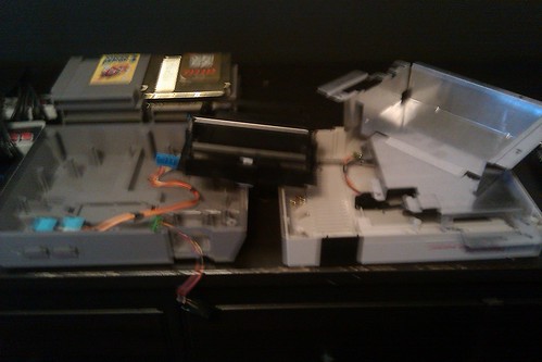
IMAG0053 by FirstTimeModder, on Flickr
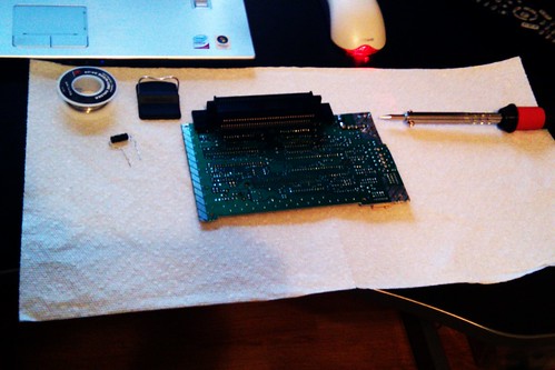
The mother board was taken out and moved to a different place.

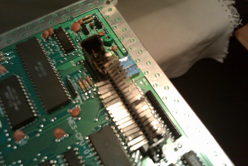
The next thing i did was disable the NES lockout chip. For a while my NES would refuse to play my games, even though they werent from another country or were pirated, so I figured with this being disabled i would be able to play them again. Thanks to the epic guide by 1uP on instructables, (http://www.instructables.com/id/How-to- ... nd-AV-Out/" onclick="window.open(this.href);return false;) I am following his steps in order to make my first portable, he has explain in detail what to do with the lock out chip.

Image
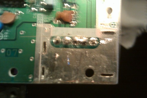
Lockout chip mod by FirstTimeModder, on Flickr
(pin 4 is missing because i have taken it out, It says you can finish there but you should wire it to ground. I can already play my games well and what not, so should I still do it or should i leave it be?)

Here is a Video containing my first test at running a game with the lockout chip disabled. Im running Legend Of Zelda. It seems to work out ok and fine so im happy. Before my nes would turn on and off and on and off.
http://www.youtube.com/watch?v=dr2SNKrZ ... ideo_title

Sorry if my voice sounds weird, I have been sick for past two days. Anyway, As you can see the Game loads fine, no more turning on and off and the graphics are no longer glitchy and what not. What I meant to finish saying was that although it looked fine and loaded fine the only thing missing was audio. Could this be result of the lockout chip mod?

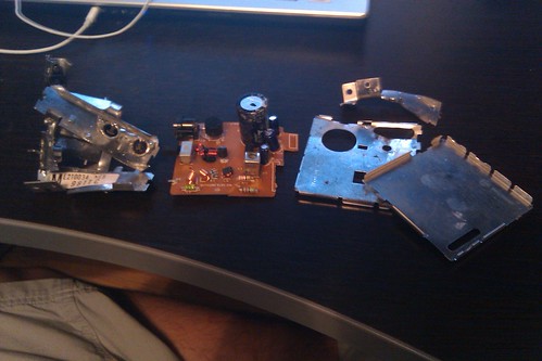
The Next thing after this was removing the RF box. After a long time of desoldering, i finally got the godamn thing to come off.
Then using pliers I took off the metal walls. Luckily, i managed to keep the board and the stuff on it mostly in tact. I did so because even though he says you wont be needing it, just incase i screw up or might end up needing it, i think ill save it.
Image
IMAG0056 by FirstTimeModder, on Flickr

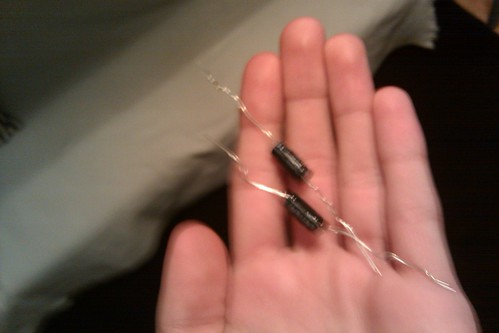
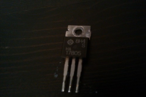
I was able to get the 17805 regulator off without damaging it,
Image
IMAG0058 by FirstTimeModder, on Flickr

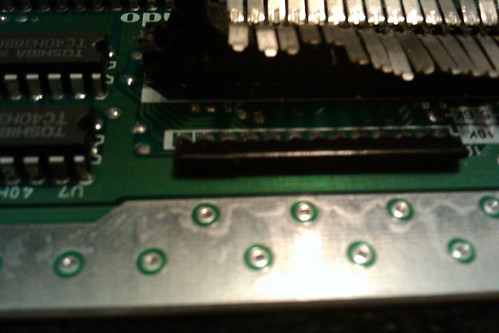
And finally, here is the area where the RF box used to be.
Image
IMAG0055 by FirstTimeModder, on Flickr

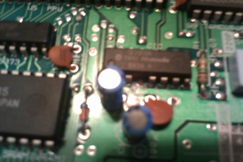
I started folding down the brown capacitors afterwards, and i plan to due the step involving the three blue ones tomorrow, (or today, considering its 1:37 am). The reason i didnt do it today was because i lack IDE cable. Hopefully if Hurricane Irene hasnt totally pwned radioshack, ill swing over there tomorrow to see if they have some.

Well this concludes my first days work. If anyone can answer my questions it would be more then appreciated. Cant wait to keep working on this thing tomorrow.

EDIT: One more Question, the black part of the regulator that says 8H4 S HA 17805, that is the heatsink for it, correct?

Haunted360
Posts:1000
Joined:Sat Jan 30, 2010 12:22 am
PSN Username:Haunted360
360 GamerTag:Haunted 360
Location:Australia
Contact:

Re: First Attempt At NesP

Post by Haunted360 » Sun Aug 28, 2011 3:04 am

That is some nice work. Just be sure to make a good case!

(Vacuum forming is always better)

FirstTimeModder
Posts:8
Joined:Sat Aug 27, 2011 10:18 pm

Re: First Attempt At NesP

Post by FirstTimeModder » Sun Aug 28, 2011 10:09 am

Thanks. I have thought through it a little bit, like should i keep the motherboard horizontal, or vertical, should i use the original controller, or make my own, which screen should i use? Ill start researching vaccum forming first though, i know very little about it at the moment, but I have seen what it can produce and the cases it makes look great.

Haunted360
Posts:1000
Joined:Sat Jan 30, 2010 12:22 am
PSN Username:Haunted360
360 GamerTag:Haunted 360
Location:Australia
Contact:

Re: First Attempt At NesP

Post by Haunted360 » Mon Aug 29, 2011 1:09 am

FirstTimeModder wrote:i know very little about it at the moment, but I have seen what it can produce and the cases it makes look great.
Sounds exactly like me when I found the Ben Heck forums :P

Nothing to it. Just plastic softened, that forms over your mould with suction. You can even test this if your still lost by just placing a plastic bag over your vacuum table (box with holes that connects to a vacuum cleaner) and you will see it in action...

FirstTimeModder
Posts:8
Joined:Sat Aug 27, 2011 10:18 pm

Re: First Attempt At NesP

Post by FirstTimeModder » Mon Aug 29, 2011 10:10 am

I found a cool guide on how to make a DIY vaccum former. I think ill start making it soon. Thanks for the idea haunted. Also, i have a question, For the Blue capacitors, it says i need IDE cable but in the picture what i see is just two regular cable. I googled IDE cable and it looks like Flat paper/wire stuff. Could he have meant to say wire? Or is there regular looking wire/ide cables out there?
Edit: Quicker way to answer the question, can i just use regular wire?
(Y/N)?
I hope, id love to get back to work on this thing, and my dad has a crap load of wire. Just not IDE cable kind.

Haunted360
Posts:1000
Joined:Sat Jan 30, 2010 12:22 am
PSN Username:Haunted360
360 GamerTag:Haunted 360
Location:Australia
Contact:

Re: First Attempt At NesP

Post by Haunted360 » Mon Aug 29, 2011 8:54 pm

lol. Of course you can use normal wire. It just has to take the amps / volts or else it will heat up and be hot.

Think of it acting like a hair dryer. The electricity heats up the coiled wire and it produces heat. The fan then pushes the heat off of the wire to give warm air (like a heatsink), except the heat source is from the Integrated Circuit (IC) or Application Specific Integrated Circuit (ASIC)).


I think he said use IDE cable, as everyone has that stuff and it is in a neat line of cables. Ribbon cable is the same thing really...

But yes. You can use any wire, that can handle the capacitance and voltage. I mean, match its thickness etc, from the IDE cable. You should be fine.

Just dont touch the capacitor while its charged. lol. It will give you a good shock, depending on the voltage and microfarads (uF). A Picofarad, is smaller then a Microfarad though, just so you know...


Best thing is to experiment. Thats how you learn. lol. Have fun!

FirstTimeModder
Posts:8
Joined:Sat Aug 27, 2011 10:18 pm

Re: First Attempt At NesP

Post by FirstTimeModder » Tue Aug 30, 2011 9:54 pm

Ok, I ended up breaking one of the capacitors in the process, so, i decided to just replace all three.
Blue means old, Green means obtained, Red means yet to have obtained.
Here is the old:
50v 1uF
50v 2.2uF
6.3v 100uF

Here is the new:
50v 1uF
50v 2.2uF

6.3v 100uF

Unfortuanatley, radioshack doesnt sell that last capacitor, but i am getting one in the mail soon so i can continue with the project soon. Ive started taking off the expansion slot, so far so good.... kinda.

Oh, also, the reason i decided to get new capacitors, is that new ones come with the real long metal pins sticking out. It would be easier for me to just solder them in, and then bend them down on the board. rather then use the wire.

New Capacitors:
Image
IMAG0062 by FirstTimeModder, on Flickr

Progress on removing expansion slot (didnt have needle nose pliars with me atm, will tomorrow):
Image
IMAG0063 by FirstTimeModder, on Flickr

Also, I had a question which I hope wont yield an answer like "nope, you screwed up."
Image
IMAG0065 by FirstTimeModder, on Flickr

Ok, so right below the expansion slot, and above the third circle from the left is that black piece. Now, on that piece, i accidentally made a tear in that little black plastic that covers it. Now it moves a little bit more independently from the rest of the actual part, it isnt broken off the mobo or anything, but can and will, or has it already made a problem?

Haunted360
Posts:1000
Joined:Sat Jan 30, 2010 12:22 am
PSN Username:Haunted360
360 GamerTag:Haunted 360
Location:Australia
Contact:

Re: First Attempt At NesP

Post by Haunted360 » Tue Aug 30, 2011 11:34 pm

FirstTimeModder wrote:Ok, so right below the expansion slot, and above the third circle from the left is that black piece. Now, on that piece, i accidentally made a tear in that little black plastic that covers it. Now it moves a little bit more independently from the rest of the actual part, it isnt broken off the mobo or anything, but can and will, or has it already made a problem?
It depends how far you cut, or what damage has been done. Only way is to wait until you power it up.

I think those row of black (usually other colours too) caterpillar things are a huge row of resistors I remember reading somewhere... Soy uo can always just match the ohms and replace the line with the cut one. Just test it with a multimeter :mrgreen:

Apart from that, seems you have it under control now 8)

FirstTimeModder
Posts:8
Joined:Sat Aug 27, 2011 10:18 pm

Re: First Attempt At NesP

Post by FirstTimeModder » Sat Sep 17, 2011 1:26 pm

Well, i am still working on this project, just having bad delays. The new capacitor i ordered still isnt here, ive called and tried to figure out whats going on but the most i get is "Still in transit". Its been like this for a while now. Its the one thing i need to keep going. When I get it ill finally be able to continue.

FirstTimeModder
Posts:8
Joined:Sat Aug 27, 2011 10:18 pm

Re: First Attempt At NesP

Post by FirstTimeModder » Fri Sep 23, 2011 12:49 pm

Image
IMAG0071 by FirstTimeModder, on Flickr

Well finally i have the third capacitor :D, and they sent an extra because they were sorry for the troubles they put me through. Now, anything i should consider b4 i get started on attatching it? My plan is to desolder the back, to make a good hole, get the ends of the capacitor in, then use solder to resolder it all in place. Sound good?

Haunted360
Posts:1000
Joined:Sat Jan 30, 2010 12:22 am
PSN Username:Haunted360
360 GamerTag:Haunted 360
Location:Australia
Contact:

Re: First Attempt At NesP

Post by Haunted360 » Fri Sep 23, 2011 7:05 pm

FirstTimeModder wrote:Well finally i have the third capacitor :D, and they sent an extra because they were sorry for the troubles they put me through. Now, anything i should consider b4 i get started on attatching it? My plan is to desolder the back, to make a good hole, get the ends of the capacitor in, then use solder to resolder it all in place. Sound good?
Sounds fine.

Just dont heat up the solder pads to long, or the pads / traces will rip up. Also, be careful when removing the old component, and remove all the solder, leaving a clean hole. If not, the pad / trace will rip up when you try to push the new component through.

FirstTimeModder
Posts:8
Joined:Sat Aug 27, 2011 10:18 pm

Re: First Attempt At NesP

Post by FirstTimeModder » Sat Sep 24, 2011 9:45 am

Well i dont have my phone right now so i cant give you guys and pics but i got it done. Thats not without saying i think i caused a lot of problems. Is it bad i if got some solder on three of a chips metal pins, its causing them to be "connected" because of the solder. everything else seems to be in order though.

The chip is the lockout chip btw.

User avatar
themadhacker
Senior Member
Posts:2670
Joined:Wed Aug 06, 2008 7:53 pm
Location:ohio

Re: First Attempt At NesP

Post by themadhacker » Thu Sep 29, 2011 12:58 pm

Yes, it would be bad to power it up with the solder bridging the pins. I suggest cleaning the soldering tip and then moving it back and forth along the pins. This typically helps the solder detach itself from the other pins. Flux helps with this if you have any. Otherwise, I would just heat up a strand of wire with the tip and place it on the pins (while still being heated) so the solder flows away from the pins to it instead. Copper wire works best for this, but others will work fine with more patience.
rest in peace, Ronnie James Dio! \m/

Post Reply