hello!
Moderator:Moderators
-
antrock101
- Posts:128
- Joined:Fri May 22, 2009 7:24 am
lol considering how rare they are to get! lol, well it seems similar than the proper screen as its all clips on the board, but nothings labled negative or positive is my main problem
HOLY FREAKIN MOTHER OF JESUS CHRIST! THAT CASE IS HUGE!
Perhaps you may buy a smaller one.

Re: hello!
It's a lot different. You are just going to get really frustrated with it. If it's not labeled, forget about it. Get your school nerd to figure it out for you 
-
antrock101
- Posts:128
- Joined:Fri May 22, 2009 7:24 am
Re: hello!
why would i get frustrated and I'm not at school i'm 22 in 4 months  there must be a way of telling if its positive or negative.
HOLY FREAKIN MOTHER OF JESUS CHRIST! THAT CASE IS HUGE!
Perhaps you may buy a smaller one.
-
antrock101
- Posts:128
- Joined:Fri May 22, 2009 7:24 am
Re: hello!
ok just gonna bump my questions forward incase anyones browsing by and see's them
my questions are, it has av out and in built in, i'm interested in av in correct? (what would be the point of av out on screen this small?)
nes only has one audio slot my screen has 2 is there a way of linking them so i don't just get audio out of 1 side.If i split the connection to 2 speakers how would the sound be.
the power button has power console and a power console and screen (see pic of a yellow bit pointing out of the front tray dc out) its 7.5v can i wire my nes straight into that so i dont have to modify the board? or will it blow the nes?
those speakers look awful i have some off my logitech case can i simple wire them in ? however i'm not sure which is positive and negative because there not color coded.(SOLVED POS ON SPEAKER PICTURE DUH!)
if the screen is rated 7.5 v will 9.6v be over kill. i cant seem to see a fuse on the board with a rating.
last one does anyone have any idea what av multi out is ? ( i ran it the screen 9v for a while seemed fine)
I'm really getting into this its fun
HOLY FREAKIN MOTHER OF JESUS CHRIST! THAT CASE IS HUGE!
Perhaps you may buy a smaller one.
Re: hello!
I really want to help but it's late over here, I'll try to answer your questions tomorrow.
-
antrock101
- Posts:128
- Joined:Fri May 22, 2009 7:24 am
Re: hello!
not a problem its 4.50 am here i should go to bed really. Just been up playing with my system  and trying to find a damn flat 72 pin cart connector none anywhere
HOLY FREAKIN MOTHER OF JESUS CHRIST! THAT CASE IS HUGE!
Perhaps you may buy a smaller one.
Re: hello!
On the screen, you want AV in, on the console, you want AV out.antrock101 wrote:it has av out and in built in, i'm interested in av in correct? (what would be the point of av out on screen this small?)
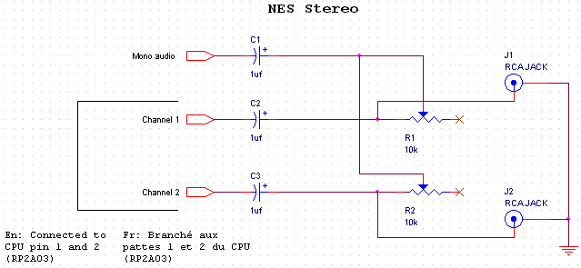
If you split the connection it would be weaker but otherwise okay. There is a stereo mod which gives psudo-stereo sound, but I can't remember any links. Ben has a version, and there's one on raphnet.com I think.antrock101 wrote: nes only has one audio slot my screen has 2 is there a way of linking them so i don't just get audio out of 1 side.If i split the connection to 2 speakers how would the sound be.
If you haven't removed the RF box you can, but I'm assuming you have (if not, you will later). The answer is no. You have to run it through a regulator. A 7805 to be specific. There's one in the RF box you can use. Be sure to heatsink it to something.antrock101 wrote:the power button has power console and a power console and screen (see pic of a yellow bit pointing out of the front tray dc out) its 7.5v can i wire my nes straight into that so i dont have to modify the board? or will it blow the nes?
9.6V will probably kill it. What type of screen is it? If it was rated for 12V originally it should be fine. If it's a PS1 screen, no. I have no idea what AV multi out you are talking about, is it on the screen? Picture?antrock101 wrote:if the screen is rated 7.5 v will 9.6v be over kill. i cant seem to see a fuse on the board with a rating.
last one does anyone have any idea what av multi out is ? ( i ran it the screen 9v for a while seemed fine)
Also, fuses are never rated for volts, only amps.
Good, I had a lot of fun with YAP64 until I fried it.antrock101 wrote:I'm really getting into this its fun
I'm 14 and I feel really guilty giving you advice.antrock101 wrote:I'm not at school i'm 22 in 4 months

Re: hello!
Their rated for both. They have an amp and a volt rating. Overload either and it blows.XCVG wrote:Also, fuses are never rated for volts, only amps.
copulate all you goddamn smartasses.
-
antrock101
- Posts:128
- Joined:Fri May 22, 2009 7:24 am
Re: hello!
so i can take the dc in and put a battery to it. and with the dc out i build this regulator http://www.instructables.com/id/SYSOH64FLROLSWL/" onclick="window.open(this.href);return false;
and then i can attach to the nes.
cheers for your help.
and then i can attach to the nes.
Unfortunetly i was never ever taught anything about electronics, anything i do know i taught myself from building my robots, remeber battlebots/robotwars? However they are pretty simple in comparison.I'm glad you are helping me make no mistake. And your very knowledgable for your age considering people a lot older than you struggle with the concepts of electronics.But always remeber its not your age that defines your learning. Your a smart kid keep at itI'm 14 and I feel really guilty giving you advice.
HOLY FREAKIN MOTHER OF JESUS CHRIST! THAT CASE IS HUGE!
Perhaps you may buy a smaller one.
Re: hello!
I've played with electronics since I was like 7. Anyway do you have Ben's book? It's a fairly good introduction. If not, there's lots of info on the internet about this stuff. And I don't know a lot about electronics, look at marshallh, now that's epic-level electronics. My electronics/robotics teacher says I'm ahead of most of his grade 11s. Anyway I remember robot wars, one of my aspirations was to build a battlebot, but pointless cause there is no events near me and I don't have enough money. And there's not even enough people to have an antwars.antrock101 wrote:so i can take the dc in and put a battery to it. and with the dc out i build this regulator http://www.instructables.com/id/SYSOH64FLROLSWL/" onclick="window.open(this.href);return false;
and then i can attach to the nes.
Unfortunetly i was never ever taught anything about electronics, anything i do know i taught myself from building my robots, remeber battlebots/robotwars? However they are pretty simple in comparison.I'm glad you are helping me make no mistake. And your very knowledgable for your age considering people a lot older than you struggle with the concepts of electronics.But always remeber its not your age that defines your learning. Your a smart kid keep at itI'm 14 and I feel really guilty giving you advice.
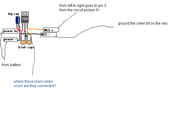
Anyway enough about me. 7805 diagram:

I've included a crappy visual representation, but you're going to have to learn to build stuff from schematics. I've added additional info in brackets. I find it EASIER to build from a schematic then from a PCB layout or visual diagram. You can figure out how the circuit works and modify it easier this way. Also good if you want to build it in a way not intended, like if it was designed for perf and you wanted to make a circuit board. In any case, refer to these pictures as well:

After you rip off the RF box you will have this. Ignore the circuit below for a sec. From left to right the holes are: weak video, mono audio, 5V in. The two rightmost holes I have no idea, maybe reset or something. The ground (erroneously "negative" or "minus", properly also "common" or "com") can be connected to the outer part like in the picture.
The weak video will need amping. If you need help I can make a schematic and diagram.
In any case good luck!
EDIT: If you want, info on stereo mod:
http://www.raphnet.net/electronique/nes ... mod_en.php" onclick="window.open(this.href);return false;
This schematic in particular:
-
eurddrue

- Senior Member
- Posts:2367
- Joined:Fri Jul 18, 2008 1:26 pm
- Location:I am so caught up in real life I have to be done for a while. I'll still check in but dontexpectmuch
- Contact:
Re: hello!
What do those little .1 uf caps on the 7805 do? I've noticed caps like that on quite a few power switches and stuff like that. (I didn't do my research  )
)
Banned indefinitely if you desperately need to contact me STOPPHONESPAMPLOX Please dont be a dick and call for something random like "HEY YURDRUE DOO U HAZ SPAM?"
wallydawg wrote:I think we should check to see if you can withstand 220 voltschainfire95 wrote:220V I believe
Re: hello!
They filter out noise and crap like that.eurddrue wrote:What do those little .1 uf caps on the 7805 do? I've noticed caps like that on quite a few power switches and stuff like that. (I didn't do my research
-
antrock101
- Posts:128
- Joined:Fri May 22, 2009 7:24 am
Re: hello!
damn thats really useful, Still awaiting bens book amazon are taking there time and after what i paid for postage I'm not happy grrr.
are those 2 different diagrams as you don't show the 7805 reg in the actual circuit diagram below.I'm thinking this is the video boost looking at the 2 different types on indestructibles and your diagrams
2n4401 is the Amplifying Transistor
33 and 220 guessing there types of resistor?
I'm just looking at the first diagram I'm just making notes on it
HOLY FREAKIN MOTHER OF JESUS CHRIST! THAT CASE IS HUGE!
Perhaps you may buy a smaller one.
-
antrock101
- Posts:128
- Joined:Fri May 22, 2009 7:24 am
Re: hello!
btw where can i get a 72 pin connector i can only find american sites and the shipping is around 10 dollars :s
HOLY FREAKIN MOTHER OF JESUS CHRIST! THAT CASE IS HUGE!
Perhaps you may buy a smaller one.
Re: hello!
Okay, the boost circuit is separate, and you have it correct I think.
The 7805 is separate. It's not on that diagram because said diagram assumes a regulated 5V source, which you clearly do not have. And yes the black wires are connected.
No idea on the connector, sorry. What happened to the one you had?
The 7805 is separate. It's not on that diagram because said diagram assumes a regulated 5V source, which you clearly do not have. And yes the black wires are connected.
No idea on the connector, sorry. What happened to the one you had?