I took it apart to clean and it worked fine with the top shield and top half off. Then I put it back together the rest of the way and it wont make any noise. Video is perfect, 72 pin connector is a fairly recent Taiwanese replacement, the connector looks and acts good. I have it stripped down to the lower shell and mobo right now, I can stick a cart in the connector and it plays great, but without sound, I can drum on the cart with my fingers and the video remains perfect.
NOT MY TV/HOOKUPS
Any ideas? Is there a chip devoted to sound in these thing or is it all in the CPU or PPU? What pin of what chip? where does it go after that? I can trace and track bad connections/cold joints, but not without any idea where to start.
NES no audio!!!
Moderator:Moderators

Re: NES no audio!!!
It could be the jack.
-
Kenny_McCormic
- Posts:223
- Joined:Tue Mar 28, 2006 4:53 pm
Re: NES no audio!!!
Tried RF and AV, dont have a scope(that works) or I would start poking. Found out that audio is pin 1 and 2 on the CPU. How hot is it from the pin?
-
Kenny_McCormic
- Posts:223
- Joined:Tue Mar 28, 2006 4:53 pm
Re: NES no audio!!!
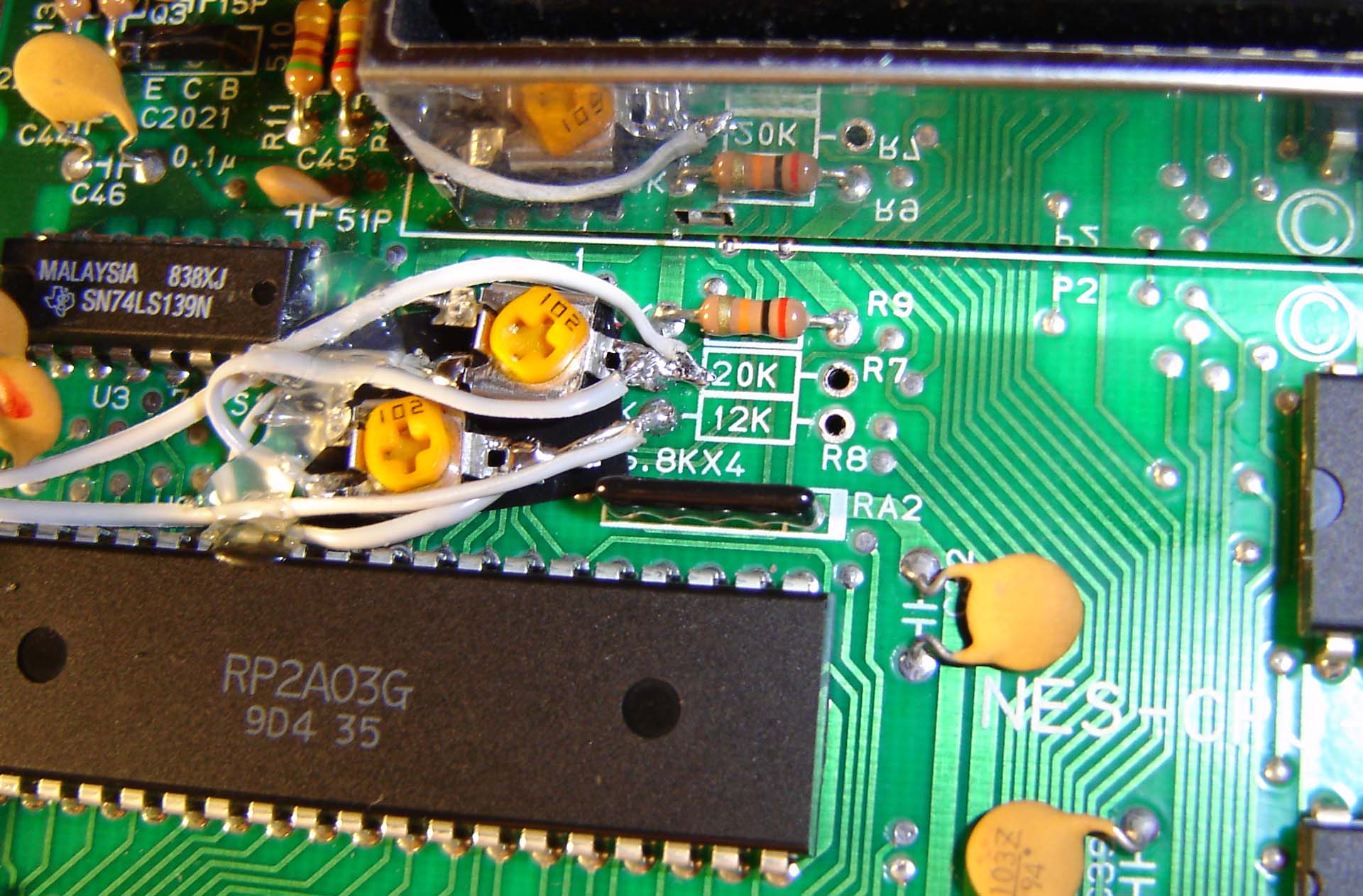
Alright, going off of Ben's faux stereo mod picture, I HAVE audio(rigged some jumper wires to my AV cable) at the points where he is pulling it as well at pin 1 and 2 of the CPU.
Last edited by Kenny_McCormic on Thu Mar 05, 2009 4:29 pm, edited 1 time in total.
-
Kenny_McCormic
- Posts:223
- Joined:Tue Mar 28, 2006 4:53 pm
Re: NES no audio!!!
I have audio after the resistors its just quieter(duh).
NO AUDIO WHERE IT GOES INTO THE RF BOX, get a pop when I hook it up to the pin but no sound.
What happens between the resistors in Ben's mod and the RF box?
NO AUDIO WHERE IT GOES INTO THE RF BOX, get a pop when I hook it up to the pin but no sound.
What happens between the resistors in Ben's mod and the RF box?
Re: NES no audio!!!
It goes into a capacitor after the resistors. Here's some relevant info that I dug up while researching the stereo mod in-depth:
Complete schematics of the NES:
http://www.freeinfosociety.com/electron ... hp?id=2405
NES audio schematic in isolation:
Another variation on the stereo mod:
http://www.raphnet.net/electronique/nes ... mod_en.php
Here's a pic from the above site of a wire soldered to the audio input pin of the RF box (one of the things you asked about):
Note that FC1 (looks like a green resistor, but it's really a 39uH inductor) is the last component on the PCB before the audio reaches the input of the RF box, although the first schematic I posted shows more going on after that point.
-
Kenny_McCormic
- Posts:223
- Joined:Tue Mar 28, 2006 4:53 pm
Re: NES no audio!!!
I started tracing back from FC1, I have audio at where it comes off the logic chip(74HCU04) but its dim, like volume maxed out and i can barely hear it dim, but its there. When I short C20(220p) this extremely quiet audio comes out the RCA jack.
Keep in mind I want to keep this thing 100% original. No modding, just get it back to kicking out mono.
Keep in mind I want to keep this thing 100% original. No modding, just get it back to kicking out mono.
Re: NES no audio!!!
Which capacitor is C20? Is it the one between the input and output of the 74HCU04, or the one between the input and ground?
I don't know a lot about electronics, so maybe someone can better suggest what might be wrong.
I don't know a lot about electronics, so maybe someone can better suggest what might be wrong.
-
Kenny_McCormic
- Posts:223
- Joined:Tue Mar 28, 2006 4:53 pm
Re: NES no audio!!!
Input and output, think the chip might be gone or lost power?
Re: NES no audio!!!
It's possible but I'd be surprised because the chip contains multiple hex inverters, and the NES uses every one of them in a completely different place in the schematic, so you'd probably be seeing other problems besides just no audio.
-
Kenny_McCormic
- Posts:223
- Joined:Tue Mar 28, 2006 4:53 pm
Re: NES no audio!!!
The chip is getting 5 volts, It would appear as if the inverter functions as a primary amp, which then goes to the single transistor amp shown in the schematic. I believe the by shorting C20 I am bypassing the inverter/amp and the secondary is just barely putting out something noticeable.

Re: NES no audio!!!
Luckily for you, the audio comes straight out of the PPU, so if you are seeing an image chances are that not all hope for sound is lost.
...
-
nevermind1534
- Senior Member
- Posts:1977
- Joined:Fri Feb 06, 2009 1:36 pm
- Steam ID:nevermind1534
- Location:Detroit, MI
- Contact:
Re: NES no audio!!!
err, the CPU.Bibin wrote:Luckily for you, the audio comes straight out of the PPU
Kyo wrote:"does anyone here know how to fly a plane?"
"STAND BACK EVERYBODY, I HAVE A FAKE ID"
-
Kenny_McCormic
- Posts:223
- Joined:Tue Mar 28, 2006 4:53 pm
Re: NES no audio!!!
The CPU is kicking out a audio signal, the amp circuit is copulate up.Bibin wrote:Luckily for you, the audio comes straight out of the PPU, so if you are seeing an image chances are that not all hope for sound is lost.

Re: NES no audio!!!
I have the same problem.
It looks like some capacitors went bad on mine.
There is a motorola(I think) chip on there.
Audio seems to be coming from pin 10 (very quiet) to a cap under (?) the chip to another cap to the rf box.
It looks like some capacitors went bad on mine.
There is a motorola(I think) chip on there.
Audio seems to be coming from pin 10 (very quiet) to a cap under (?) the chip to another cap to the rf box.