Dreamcast A/V pinout
Posted: Wed Jun 03, 2009 4:06 pm
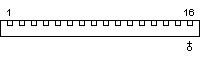
Left to right:
Pin Description
1 Ground
2 Right Audio
3 Left Audio
4 +12 VDC
5 +5 VDC
6 31kHz (VGA) select (active low) (Connected to PORT9 on CPU)
7 RGB select (active low) (Connected to PORT8 on CPU)
8 Vertical Sync (for VGA)
9 Horizontal Sync (for VGA)
10 Composite Sync
11 S-video Chrominance (C)
12 S-video Luminance (Y)
13 Composite Video
14 Blue *
15 Green *
16 Red *
*connect in series with 220µF coupling capacitors.