Basement Modder's rough PS2p wiring diagram and other info
Posted: Wed Jun 03, 2009 2:53 pm
Due to the increasing number of people asking how to make a PS2p, here you go:
RGB:

NOTE: The lines DO NOT necessarily go to the screen input the picture shows. Diagram below.
Composite:
<coming soon>
A/V INFORMATION
Heres the A/V output

Pin Description
1 Ground
2 Left Audio
3 Ground
4 Right Audio
5 S-Video Y
6 Composite Video
7 S-Video C
8 Video Ground
9 Blue
10 +5 Volt
11 Red
12 Green
NOTE: You must add a 220uf capacitor in each of the RGB lines (+ towards console) to get a good picture. If you don't, the picture will be too dark.
You can connect composite here: (Remember to connect ground)
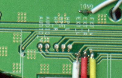
You must bridge HP_S, HP_L, and HP_R if you aren't adding a headphone jack to your portable.
source
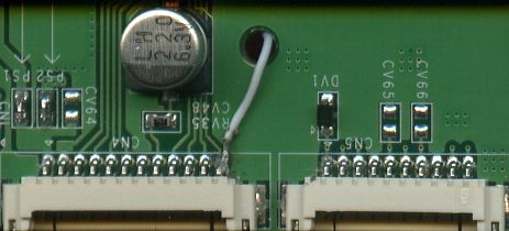
And RGB here: (remember to connect ground.)

source
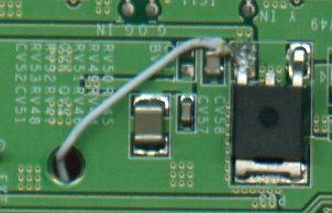
If your PSone screen powers up and goes blank, this may fix it:
source
PRICING INFORMATION:
-This can cost anywhere from $80-$400 depending on what quality you want. Batteries are a BIG factor
SIZE INFORMATION
-Size depends on how streamlined you make it. You should get a pretty small portable from the slim version. (EG: 8"x5"x1.5")
TIME + LABOR INFORMATION
-This can take you from 1-6 months, depending on how often you work and how good you are with a soldiering iron.
ENJOY YOUR PORTABLE
RGB:
NOTE: The lines DO NOT necessarily go to the screen input the picture shows. Diagram below.
Composite:
<coming soon>
A/V INFORMATION
Heres the A/V output
Pin Description
1 Ground
2 Left Audio
3 Ground
4 Right Audio
5 S-Video Y
6 Composite Video
7 S-Video C
8 Video Ground
9 Blue
10 +5 Volt
11 Red
12 Green
NOTE: You must add a 220uf capacitor in each of the RGB lines (+ towards console) to get a good picture. If you don't, the picture will be too dark.
You can connect composite here: (Remember to connect ground)
You must bridge HP_S, HP_L, and HP_R if you aren't adding a headphone jack to your portable.
source
And RGB here: (remember to connect ground.)
source
If your PSone screen powers up and goes blank, this may fix it:
source
PRICING INFORMATION:
-This can cost anywhere from $80-$400 depending on what quality you want. Batteries are a BIG factor
SIZE INFORMATION
-Size depends on how streamlined you make it. You should get a pretty small portable from the slim version. (EG: 8"x5"x1.5")
TIME + LABOR INFORMATION
-This can take you from 1-6 months, depending on how often you work and how good you are with a soldiering iron.
ENJOY YOUR PORTABLE