SNES Arcade Cabinet

Hacking a [insert console name here] but don't see a "[insert console name here] Hacking" forum? Come on in and post your [insert console name here] questions and build logs!

Moderator:Moderators

Post Reply
User avatar
Punchinello
Posts:27
Joined:Tue Jun 29, 2004 2:14 pm
SNES Arcade Cabinet

Post by Punchinello » Fri Feb 02, 2007 9:52 am

I want to do something similar to this:

http://www.willyliliana.com/NES%20Cabin ... abinet.htm

but with an SNES... and without the short shorts.

I will be able to get my hands on a cabinet, mount the console on the inside with an opening for the cartridge.

Now here is the problem. I originally planned on using the SNES Super Advantage for the controller. (lol, pics):

Image

This would be pretty easy as these things are all over ebay for about $10 a pop. I figured I could just mount two of these bad boys on the cabinet, or take out the chip and build it into the cabinet.

Then I got to thinking. I saw this on one of those "build your own cabinet" websites. http://arcadecontrols.com/arcade_achilles.shtml

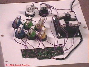
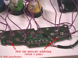
So basically, I really want to build my own controls using buttons and an 8 way joystick from a regular SNES controller that works on the SNES like an SNES controller.

Now after that long winded back story, my question is: would it be very difficult to turn an SNES pad into an arcade joystick like in the link above? Can I just soulder some buttons onto the pad or is there more to it than that? Thanks!

User avatar
Krepticor
Senior Member
Posts:1567
Joined:Sun Jan 01, 2006 8:06 pm
Location:Shadow Hearts

Post by Krepticor » Fri Feb 02, 2007 10:17 am

alright I recommen this

The SNES advantage has everything you need, however, If you just want buttons without all the other features, Seriously vasriable turbos...wimpy wimpy wimpy :P

All you need to do is connect the live feed for each button to one pole of the switch and the ground on the other, then you just go from there, I say this since the little chips in the SNES can be removed easily and re-wired easily and they take up nearly no space when compared to an arcade cab

However, if you want the trubo features, then you have two options, do the afoirmentiond and biuld your own circuits...hard
or possibly use the SNES advantage...waste of a good controller IMO

~Krepticor
I refuse to dignify myself with an intelligent and witty signature

User avatar
Punchinello
Posts:27
Joined:Tue Jun 29, 2004 2:14 pm

Post by Punchinello » Fri Feb 02, 2007 10:35 am

So basically, I can just use an SNES controller chip, buy the button switches, and connect 2 wires from the buttons to the chip... for each button on the pad. Am I getting that correct? I realize that there are specific places I need to wire, but theres not other circuity involved beside re routing the switch (or button) that is normally part of the controller to the arcade style button?

bgnome
Posts:122
Joined:Wed Jan 24, 2007 10:56 am
Location:College Station, TX

Post by bgnome » Fri Feb 02, 2007 11:28 am

since all the buttons are digital, all you need to do is replace the button on the gamepad by the microswitch for the arcade control. judging by the link, it looks like the buttons share a common ground so all you need to do is solder 1 wire to each pad and ground it.

User avatar
Punchinello
Posts:27
Joined:Tue Jun 29, 2004 2:14 pm

Post by Punchinello » Fri Feb 02, 2007 12:44 pm

So this seems like it could be fairly easy. I apologize though, because I don't really know too much about electronics yet, but I am studying engineering at a university right now, so learning shouldn't be that difficult. Could you please elaborate a little? I am not sure what you mean by common ground.

bgnome
Posts:122
Joined:Wed Jan 24, 2007 10:56 am
Location:College Station, TX

Post by bgnome » Fri Feb 02, 2007 2:40 pm

Image
Image

if you look closely at those pictures you will see the gamepad board and the microswitches from the buttons/joystick. you also see all the wires connecting them. the pads for the buttons on the pcb has 1 wire soldered to it which connects to the microswitch. if you then look at the microswitches, you will see that they are interconnected by another wire as well. that is the common ground. it is shared among all the microswitches as well as the board normally. so, in this case, since the ground is all the same, you can either solder a ground wire for each individual button, or connect all the buttons and solder 1 or 2 ground wires. (in theory 1 will work fine, but i say 2 because it is a better practice to do a "ground loop" in arcade controls by having 1 wire ground the button switches and 1 wire ground the joystick switches even though they are all connected to eachother.)

the microswitches usually have 3 contacts, so you need to keep them straight. one is for ground or commin, (on the bottom), and the two on the back of the switch are either "normally closed" or "normally open". connect the "normally open" to the pcb at the appropriate pads.

it really is pretty straightforward. just study those pictures and read up some at arcadecontrols.com if you wish. you will learn that most gamepads work in the same way -- i have 4 of the old style ps1 pads i was planning on doing this with.

User avatar
Punchinello
Posts:27
Joined:Tue Jun 29, 2004 2:14 pm

Post by Punchinello » Sat Feb 03, 2007 12:13 pm

Ok, I studied the circuit and a picture of the SNES controller circuit. This really should be pretty easy to do. I really appreciate the help.

jeroen
Senior Member
Posts:1573
Joined:Mon Oct 10, 2005 7:42 am
Location:The Netherlands

Post by jeroen » Sat Feb 03, 2007 12:16 pm

I'm not sure. But you might wanna put some pull-up resistors on the button lines.

User avatar
Punchinello
Posts:27
Joined:Tue Jun 29, 2004 2:14 pm

Post by Punchinello » Sun Feb 04, 2007 3:40 pm

Why would I need resistors?

User avatar
joevennix
Portablizer
Posts:999
Joined:Sat Jan 14, 2006 9:34 am
Location:On permanent vacation from reality.
Contact:

Post by joevennix » Sun Feb 04, 2007 5:04 pm

You don't need resistors. Just solder to the button pads, not the IC pins, and you should be fine.
Image

Nucklez
Posts:118
Joined:Tue Sep 26, 2006 2:50 pm
Location:US
Contact:

Post by Nucklez » Wed Feb 07, 2007 9:05 pm

I did practically the same thing, but with a keyboard. It works great, and the SNES controller idea is what I'm planning on doing with an XBox controller on my current project. Solder the wires from the buttons to the pads on the IC. You can check out the pics of my arcade buttons connected to a keyboard encoder. I got the buttons and joystick from happs controls.

http://www.nucklez.com/arcade/
Image

User avatar
Krepticor
Senior Member
Posts:1567
Joined:Sun Jan 01, 2006 8:06 pm
Location:Shadow Hearts

Post by Krepticor » Thu Feb 08, 2007 10:27 am

yea use the controller board and there will be no problems with needing extra crap...
I refuse to dignify myself with an intelligent and witty signature

User avatar
hellfire
Posts:71
Joined:Sun Sep 19, 2010 9:18 pm

Re: SNES Arcade Cabinet

Post by hellfire » Thu Sep 30, 2010 6:47 pm

sorry,, i know im digging up an old thread.. and asking a lot for a newbie.. but ive recently purchased a cabinet and a retro duo(can order joysticks/buttons/wires next week) and desperately need to figure out exactly how to wire up my snes controller to some happ joysticks/buttons.. i can see in the diagram above how to connect all the buttons and joystick wires to the board with no problems.. its just im not so sure about the ground wires.. i can see that you connect it to all of the ground/common on the microswitches for the buttons.. but i cant see much about the ground wires on the joystick to d-pad.. where do i ground the loop to? the d-pad? or is there something close to it? i just cant tell in the small images.. i am new to wiring and soldering, so any help would be much appreciated. though, a simple diagram showing the ground and lead wires in different colors would be wonderful.
the reason i need to be real sure is because im on a tight budget, and really dont want to mess something up.
ive searched for a few days trying to find a good diagram about doing this.. and all ive really found is this thread and one video on youtube: http://www.youtube.com/watch?v=OPvRdYPmJNM" onclick="window.open(this.href);return false;
i got some useful info from the video, and i want my finished product to be similar... but it still dont really show how to wire up the ground all the way.

im also gonna try make a tutorial about putting one of these together.. ill give you total credit for helping with the wiring.
heres the cab i got for $40.. gotta make tv braces, back door and control panel(that i know how to do)
Image
http://mylittlegamer.blogspot.com/" onclick="window.open(this.href);return false;

Post Reply