Shift register question EDIT: A failure!! Need help! :D

Includes Atari 2600, Nintendo 8-bit, Sega Master System, MSX and more!

Moderator:Moderators

clabland
Posts:6
Joined:Mon Jan 26, 2009 3:25 am
Shift register question EDIT: A failure!! Need help! :D

Post by clabland » Mon Jan 26, 2009 3:33 am

Not really a portable NES question, but I figured this was the best place to ask this. I would like to be able to use my NES controllers to play roms on my PC, but I don't want to alter the controllers in any way. My plan is to dremel some holes in one of the blank CD-ROM drive bays of my PC, and install a female NES controller plug there to plug in my controllers. Also, I don't feel like spending $25 on a pre-made kit to convert to USB, so I'm going to hack/cut up an old USB keyboard and do it by hand. So my question is, would I be able to use a serial-to-parallel shift register to "read" the signals from the controller and convert them back to parallel, so that I could then feed the parallel inputs into the old USB keyboard? I realize it'd be easier to just convert the darn controller to USB directly, but I feel like preserving my controllers (they were my childhood, after all :D ), and also would like to learn more about shift registers in the process. So does anyone know if this is even possible/likely to work? Thanks!

EDIT:

Hey all!

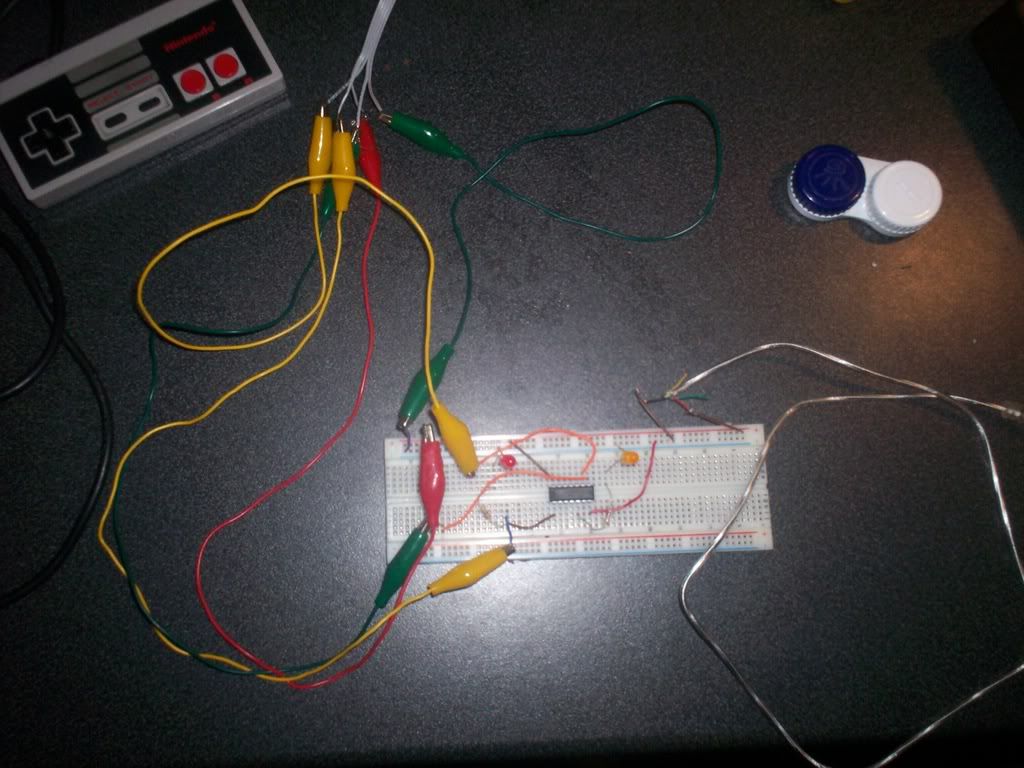
Ok, so I purchased a serial-to-parallel shift register as planned. I hooked up the shift register as follows:
Image
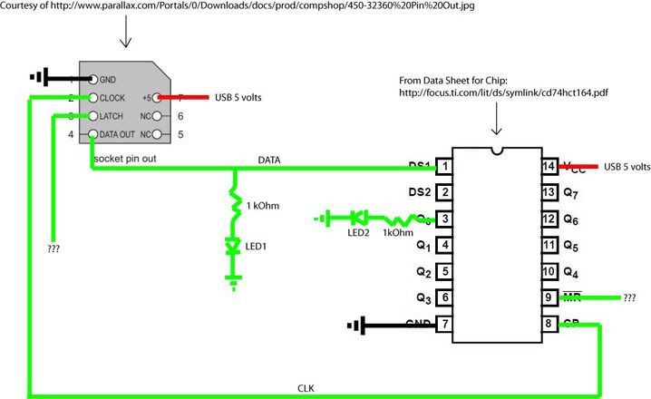
Except that where latch comes out of the controller (and turns into ???) I have it connected to pin 9 (the other ???). Pin 9 is the "clear" pin on the shift register. With that setup (shown below) LED1, which comes on when the controller plugs in, turns off when any button is pressed on the controller. Also, anything grounded goes to the USB ground, and the 5 volts comes from the USB cord as well. (Not using the data lines quite yet obviously, just getting some power from the USB).
Image

So I know that the basic idea when the controller is hooked up to an NES is that the NES sends a pulse down the latch, telling the controller to store the current button press states. The NES then pulses 8 times down the clock, one time for each button, to receive the serial data. LED2 should in theory light up if one of the buttons is pressed (not sure which one, but there are only 8 outputs on the register, the same number of buttons on the controller, so ONE of the buttons should output to the current position of LED2). So basically the current setup obviously won't work, and I was wondering if anyone had ideas at all about how to make this happen.

Some infos:
Data sheet for my shift register: http://focus.ti.com/lit/ds/symlink/cd74hct164.pdf

Some thoughts:
- Should I have something else producing a constant clock pulse (I think it should be 60Hz, I think thats what the NES does) hooked up to the controller CLK and the chip's CLK?
- Do I need something to send a pulse down the latch every 8 clock cycles?
- I'm not entirely sure what place the CLR on the register should play in the whole scheme lol.
- I know a lot of people will say "just use a programmable PIC," which may be what I end up doing. I want to avoid this for the obvious cost reasons, and I really think this shift register thing could work!
- Definitely starting to think I'll be needing an oscilloscope for this, with all the high and low states involved with those shift registers

Thanks for reading, sorry it is so long!! If there's any confusion in my description, just yell at me and ill try to give more information! :D
Last edited by clabland on Tue Feb 03, 2009 1:15 am, edited 1 time in total.

User avatar
gannon
Moderator
Posts:6974
Joined:Sun Apr 04, 2004 4:48 pm
Location:Near that one big lake
Contact:

Post by gannon » Mon Jan 26, 2009 4:46 am

Yep, it'll work.
You could also you a usb capable PIC to translate the controller data into USB HID input if you have a PIC burner and can program. You can also interface the controller directly into the MIDI or Parallel port if I remember correctly.

User avatar
grossaffe
Posts:1450
Joined:Thu May 29, 2008 11:54 pm
Location:USA
Contact:

Post by grossaffe » Mon Jan 26, 2009 8:57 am

gannon wrote:Yep, it'll work.
You could also you a usb capable PIC to translate the controller data into USB HID input if you have a PIC burner and can program. You can also interface the controller directly into the MIDI or Parallel port if I remember correctly.
Don't know about MIDI port, but there is definitely a way to do parallel port. I believe it has the same wiring diagram as SNES to parallel but just requires a different driver.

edit: you could actually wire up 5 SNES/NES controllers to the same parallel port if you wished, and you could mix and match (3 SNES and 2 NES or whatever) if you felt like it.
Last edited by grossaffe on Mon Jan 26, 2009 3:24 pm, edited 1 time in total.

User avatar
Bibin
Posts:1127
Joined:Sun Mar 04, 2007 2:14 am
Location:Brooklyn, NY
Contact:

Post by Bibin » Mon Jan 26, 2009 2:46 pm

Sorta like this, but with a NES controller?

Image
...

clabland
Posts:6
Joined:Mon Jan 26, 2009 3:25 am

Post by clabland » Mon Jan 26, 2009 4:54 pm

gannon - well its good to know it'll work, i'll give it a try. A PIC would be ideal, but i'll save that for another day.. for some reason I really want to try this specific plan out lol. Thanks!

grossaffe - Yeah I have a parallel cable I rigged up to an old Four Score a few years ago, but that was 3 computers or so ago and this new computer no longer has a parallel port :( . But USB is preferable anyways, since it can all be wired inside the case to the motherboard itself, rather than a cable hanging out the back to reach the parallel port (if I had one).

Bibin - Yes! That is the exact idea. I would have two NES ports on the far left for now, then someday two SNES in the middle, and then eventually an N64 or two on the right.

User avatar
grossaffe
Posts:1450
Joined:Thu May 29, 2008 11:54 pm
Location:USA
Contact:

Post by grossaffe » Mon Jan 26, 2009 5:04 pm

clabland wrote:grossaffe - Yeah I have a parallel cable I rigged up to an old Four Score a few years ago, but that was 3 computers or so ago and this new computer no longer has a parallel port :( . But USB is preferable anyways, since it can all be wired inside the case to the motherboard itself, rather than a cable hanging out the back to reach the parallel port (if I had one).
well that's too bad. and its not like you'd have to have the cable sticking out the back, you could always just desolder the parallel port and directly solder the connections to your motherboard. If I ever get a decent computer case I may do the same to my computer. 'till then I've got my 5 SNES ports in a project box along side my computer.

clabland
Posts:6
Joined:Mon Jan 26, 2009 3:25 am

Post by clabland » Mon Jan 26, 2009 5:06 pm

ah, well that is true. and i sure hope you're having some bomberman action over there lol.

User avatar
Aguiluz
Posts:1141
Joined:Tue Nov 20, 2007 7:58 pm
Location:Ontario, Canada
Contact:

Post by Aguiluz » Mon Jan 26, 2009 6:53 pm

Get a USB gamepad, gut it and stuff it in a controller and hook up the buttons?

clabland
Posts:6
Joined:Mon Jan 26, 2009 3:25 am

Post by clabland » Mon Jan 26, 2009 10:46 pm

Well I would do that, except I want to have the "sleekness," so to speak, of plugging in an original controller directly to an nes-style port on my computer.

clabland
Posts:6
Joined:Mon Jan 26, 2009 3:25 am

Re: Shift register question EDIT: A failure!! Need help! :D

Post by clabland » Tue Feb 03, 2009 1:17 am

Oh and it looks like those alligator clips are touching in the picture, but they aren't :)

kelroy
Posts:3
Joined:Fri Feb 13, 2009 10:52 am

Re: Shift register question EDIT: A failure!! Need help! :D

Post by kelroy » Fri Feb 13, 2009 10:57 am

hello i am attempting this exact same hack i started this before even finding your post. If your still working on it lets coroberate and post a solution email me if interested. If we could accomplish this you would be able to do it with snes controllers also they are exactly the same but 16 bit and you would be able to use your nes/snes controller on any application that supports usb keyboards e.g., modded xboxs and such.

User avatar
Life of Brian
Moderator
Posts:2867
Joined:Wed Aug 03, 2005 5:55 pm
Location:Oklahoma
Contact:

Re: Shift register question EDIT: A failure!! Need help! :D

Post by Life of Brian » Fri Feb 13, 2009 2:25 pm

Definitely keep us all posted - it's a cool project.
dragonhead wrote:sweet. ive spent a third of my life on benheck!
Image

nevermind1534
Senior Member
Posts:1977
Joined:Fri Feb 06, 2009 1:36 pm
Steam ID:nevermind1534
Location:Detroit, MI
Contact:

Re: Shift register question EDIT: A failure!! Need help! :D

Post by nevermind1534 » Fri Feb 13, 2009 2:59 pm

For my NES PC, to hook up both controller ports, I used the onboard connector and one on a PCI card that I got from newegg.
Kyo wrote:"does anyone here know how to fly a plane?"

"STAND BACK EVERYBODY, I HAVE A FAKE ID"

kelroy
Posts:3
Joined:Fri Feb 13, 2009 10:52 am

Re: Shift register question EDIT: A failure!! Need help! :D

Post by kelroy » Tue Mar 03, 2009 8:58 am

REVISED
here is the solution sorry if i offend anyone for the lack of convention used i wanted to make it easy to understand allowing anyone to build the circuit. Feel free to edit or change but please give me credit:
Image

Nes controller Decoder
-Chips are all orientated the same direction even though that is hard to tell the jks are the same orientation as the other chips with the top to the left
(will make changes as soon)
high quality download link:
Nes controller Decoder scematic.zip
Nes controller Decoder scematic.zip Revision 2
Nes controller Decoder scematic.zip Revision 3
also note that you can not apply just a high logic to drive a keyboard encoder the outputs must be relayed in some way. I will find a solution and post it
Thanks
mouser is a good location to get all the parts
Alhadrad at Gmail dot Com

i will post revisions periodically for i am always making changes improving the design

revision 2 i fixed the issue with pin 9 and and inverted the data going into the shift register now the outputs are low until a button is pressed

revision 3 fixed some spelling also vss and vdd were swapped on the frequency divider so i fixed that.

i would like feedback or suggestions for improvement also post your projects related or using this decoder i am interested in what other people may use it for.


I was motovated to design this because i wanted to use the nes controller with the xbox but this decoder has potential to be applied to many things namely: mame machines(ipac encoders), control various things like motors, leds, perhaps rc cars, Frankenstein an nes to work on Genesis because the genesis is parallel communication and the nes is serial this decoder translates the nes outputs to parallel, the possibilities are endless

this same circuit could be applied to the snes controller with some very minor revisions it there is enough interest i will post this.


One final note the components used were readily available to me there are probably easier or better ways to divide frequencies but i used what i could get my hands on. Every part can be obtained at either radio shack or mouser electronics which i recommend. Any troubles in replicating my results i would be more then happy to help debug.

User avatar
gannon
Moderator
Posts:6974
Joined:Sun Apr 04, 2004 4:48 pm
Location:Near that one big lake
Contact:

Re: Shift register question EDIT: A failure!! Need help! :D

Post by gannon » Thu May 14, 2009 7:24 am

Looks like you're using a frequency divider to make the latch line...seems a bit over complicated. You can just use a decade counter for it IIRC.

Post Reply