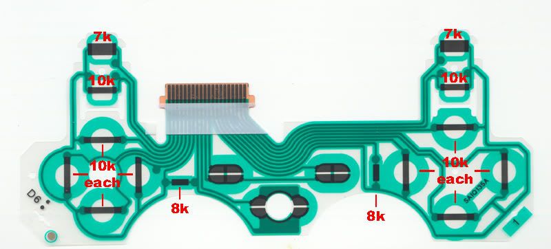
If ya want to swap anything from the left side of the controller over to the right side, say swap the Triggers L2 and R2, you have to jump thru so many hoops it's not really even worth it. The problem is with how the PS3 controllers are setup, they have 3 common lines...
COM 1 - Is for the L1, L2, and the D-pad directions
COM 2 - Is for the R1, R2, Circle, Square, Triangle and Cross
COM 3 - (Just what I call it) Is for L3, R3, Select and Start
PLUS some funky pull up Resistors that are built into the daughter board for the COM 1 and 2 lines.
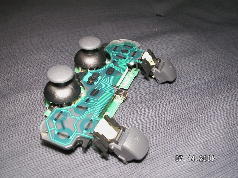
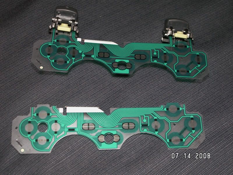
What this means is if ya want to swap L2 and R2 you also have to swap it's COM line, and ya can't because of the way the daughter board is made on these things. There's no way to just cut a trace on it and jumper it to wherever ya want, the things are a thin film and the button contacts are all 10k except for the L2/R2 which are 7k. So ya either loose the analog feature of the button or tip toe around the minefield the thing is to retain it.
So how do ya do it? The best way I've found so far is to add in another daughter board, real PITA but it works. This doesn't crap all over the analog feature of the buttons either, I've come up with other ideas/methods that do still swap them, but ruins that analog feature, and since that's not too kool in my book I went with adding in another daughter board to keep everything on the level.
That meant adding another connector as well, since ya can't solder at all onto the daughter board because of how it's made, ya can't even scrape down the coating to solder to it, even if ya could it would just melt in pretty much an instant, so you're left with having to work all around the daughter board since the button traces and contacts are 'locked' into place, ya can't do squat with that board at all.
NOTE: Something like this will be nigh impossible on the newest version of DS3 controller as they have done away with the connector, so there's no easy way at all to add in a second daughter board on that version of controller, with the exception of maybe some conductive glue and a lot of tedious wiring.
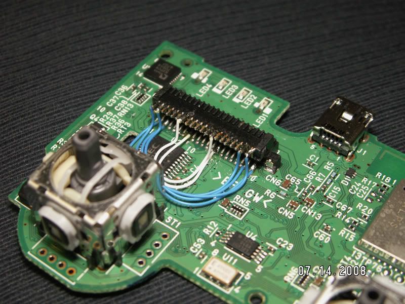
On this controller I needed to swap L1 and R1, then L2 and R2, so the first thing I needed to do was get access to those lines and their COM lines as well and soldering right to the connector was easier than hitting the TP spots as they're on the other side of the board anyway and it's preferable to keep as much as ya can on this side.
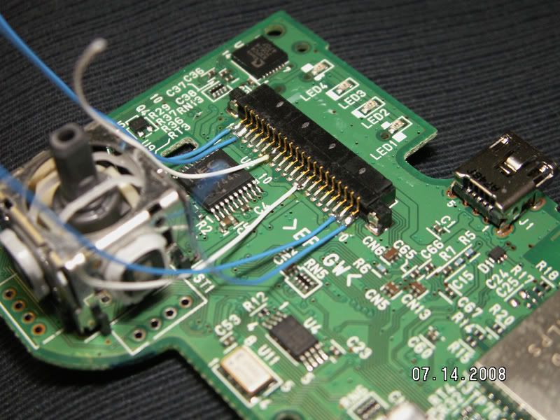
Then on goes another connector for the second daughter board..
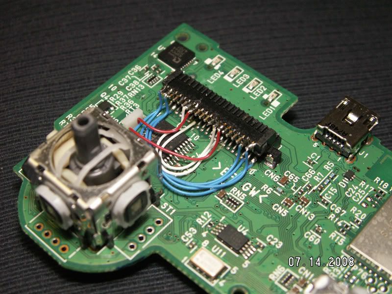
..and then 'cross the streams' as it were so the top connector is wired in reverse of the bottom one.
After that I plugged up both of the daughter boards for a test run. Note the one has the L1/2 and R1/2 removed because it's the 'main daughter board and since we're swapping them and ya don't want 2 sets of them connected at the same time, which would happen if they were left on there, so bye bye. The rest of the second daughter board is left intact because none of those duplicate buttons are getting connected to anything, so no need to mess with them.
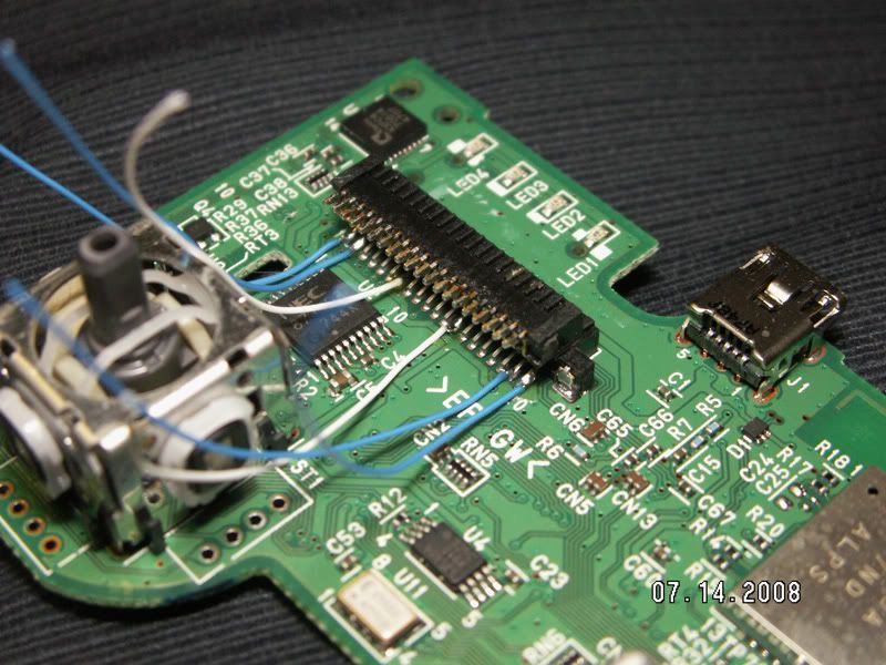
After that it was off to be plugged into the PS3 for some testing and naturally it didn't work. The buttons all acted like they were fully pressed, not kool at all. So I get to looking and can honestly come up with no real reason why this wasn't working like it should. Then I think about the ignorant pull up Resistors that are built into the daughter board, which shouldn't make a lick of difference with it setup the way it is as the ones on the primary daughter board are in place doing that job already, but I decide to send power up to the ones on the secondary daughter board and see what happened, so in go a couple more wires to take care of that..
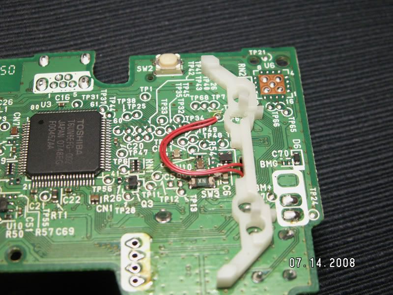
..then back together with both daughter boards for testing again..
..and presto it worked, for whatever reason. L1 is now R1, L2 is now R2 and vice versa, plus they're still analog like they were before.