hey guys.. I finaly got my retro duo, but I got a newb question. Were do I connect the wires from the screen to the retro duo? This is the first time im making a portable.
Sorry if this sounds to noobish.
BTW. I have the PS1 screen with the LED Mod.
Retro duo Help!
Moderator: Moderators
-
Designer noob
- Posts: 171
- Joined: Tue Apr 14, 2009 12:12 am
Re: Retro duo Help!
There are tons of pinouts for that kind of stuff. Just put in pinouts in the NES section. You also, can go to Bacteria's website for the screen pinout.
The N64/GBA Remix
 ............................................................................................................................................. Xbox360 WVI
............................................................................................................................................. Xbox360 WVI-
bicostp
- Moderator
- Posts: 10491
- Joined: Mon Mar 07, 2005 5:47 pm
- Steam ID: bicostp
- Location: Spamalot
- Contact:
Re: Retro duo Help!
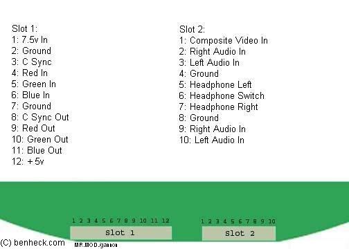
Here are the pinouts for the PSone screen:
http://forums.benheck.com/viewtopic.php ... 78&start=0" onclick="window.open(this.href);return false;
I think we have the Retro Duo info around here somewhere... It should be fairly straightforward though.
http://forums.benheck.com/viewtopic.php ... 78&start=0" onclick="window.open(this.href);return false;
I think we have the Retro Duo info around here somewhere... It should be fairly straightforward though.
Twitter
http://www.pcwgaming.com" onclick="window.open(this.href);return false;
If you want a Dropbox account, please use my referral link
http://www.pcwgaming.com" onclick="window.open(this.href);return false;
If you want a Dropbox account, please use my referral link
Re: Retro duo Help!
bicostp wrote:Here are the pinouts for the PSone screen:
http://forums.benheck.com/viewtopic.php ... 78&start=0" onclick="window.open(this.href);return false;
I think we have the Retro Duo info around here somewhere... It should be fairly straightforward though.
Thnx bicostp, but thats the problem.. What the hell is RED in blue out..
Is red in like the red cable? Im lost :S

-
bicostp
- Moderator
- Posts: 10491
- Joined: Mon Mar 07, 2005 5:47 pm
- Steam ID: bicostp
- Location: Spamalot
- Contact:
Re: Retro duo Help!
Red Green and Blue are for RGB video.
The ones you probably want are pins 1, 2, 3, and 8 on Slot 2 (composite video, right audio, left audio, and ground). (I haven't worked with the PSone screen much, but there are others here who have.)
The ones you probably want are pins 1, 2, 3, and 8 on Slot 2 (composite video, right audio, left audio, and ground). (I haven't worked with the PSone screen much, but there are others here who have.)
Twitter
http://www.pcwgaming.com" onclick="window.open(this.href);return false;
If you want a Dropbox account, please use my referral link
http://www.pcwgaming.com" onclick="window.open(this.href);return false;
If you want a Dropbox account, please use my referral link
Re: Retro duo Help!
What I still dont know is what is that ground for? What do I solder there?bicostp wrote:Red Green and Blue are for RGB video.
The ones you probably want are pins 1, 2, 3, and 8 on Slot 2 (composite video, right audio, left audio, and ground). (I haven't worked with the PSone screen much, but there are others here who have.)
-----------EDIT------------
Ok I got this image from life of brian and this is what I undestood from the diagram
Pin1 - video
Pin2- Right audio
Pin3- Component out ?!?!
Pin4- Yellow out ?!?!?
Pin5- Left audio
Pin6- GND
pin7- 8V
ok so what I dont know is pin1, pin3 and pin4
Ok so pin1 (in the second slot) on the screen, I solder that to pin3 in the retro duo
then pin2 in the screen to pin 2 in the retro duo
pin3 in the screen to pin5 in the retro duo
and what do I connect pin 8 in the screen to?
-
Kurt_
- Portablizer
- Posts: 5748
- Joined: Thu Nov 24, 2005 10:32 am
- Steam ID: kurbert
- Location: Ontario, Canada
- Contact:
Re: Retro duo Help!
To get it working:
Pin 1, Second Port (Composite In) on the screen connects to Pin 1 (VIDEO) on the Retro Duo.
Ground on the screen (any ground connection will work) connects to Ground on the Retro Duo (any ground connection will work).
You have the audio connections right.
Pin 8 on the screen (Ground) can connect to any ground connection on the Retro Duo. This is Pin 6 on the Retro Duo, apparently.
That's all you need to get it up and running, assuming you've got your power hooked up to both of them as well.
Sorry I missed you on MSN, I forgot that most people go to sleep around midnight.
Hey, sup?
-
Life of Brian
- Moderator
- Posts: 2867
- Joined: Wed Aug 03, 2005 5:55 pm
- Location: Oklahoma
- Contact:
Re: Retro duo Help!
It should be noted that the picture I posted was of a first revision Retro Duo. They are now labeled correctly.
Assuming you're using composite video (it's easiest):
Pin 1 - composite video
Pin 2 - right audio
Pin 3 - ignore
Pin 4 - ignore
Pin 5 - left audio
Pin 6 - Ground
Pin 7 - 5v, NOT 8v! If you put in 8v, you'll fry it.
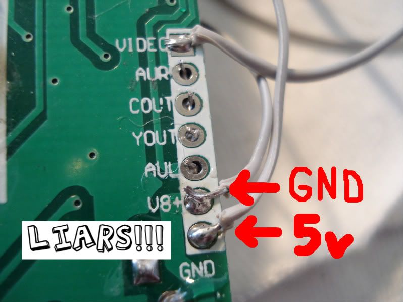
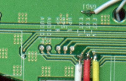
Essentially, all you need to connect between the Retro Duo and PSOne screen is pins 1, 2, 5, & 6 on the Retro Duo to pins 1-4 on Slot 2 of the PSOne screen. Or, you could connect to these spots on the back of the PSOne screen's board:
Supply 5v to the Retro Duo and around 7.5v or so to the PSOne screen and you're up and running.
I hope we've explained it well enough.
AND... I'm moving this to the SNES section because that's where it belongs.
Assuming you're using composite video (it's easiest):
Pin 1 - composite video
Pin 2 - right audio
Pin 3 - ignore
Pin 4 - ignore
Pin 5 - left audio
Pin 6 - Ground
Pin 7 - 5v, NOT 8v! If you put in 8v, you'll fry it.
Essentially, all you need to connect between the Retro Duo and PSOne screen is pins 1, 2, 5, & 6 on the Retro Duo to pins 1-4 on Slot 2 of the PSOne screen. Or, you could connect to these spots on the back of the PSOne screen's board:
Supply 5v to the Retro Duo and around 7.5v or so to the PSOne screen and you're up and running.
I hope we've explained it well enough.
AND... I'm moving this to the SNES section because that's where it belongs.
dragonhead wrote:sweet. ive spent a third of my life on benheck!

Re: Retro duo Help!
how do you desolder the snes slot? Icant take that out, Im using so many ways to remove it. Can some one help me?
-
Kurt_
- Portablizer
- Posts: 5748
- Joined: Thu Nov 24, 2005 10:32 am
- Steam ID: kurbert
- Location: Ontario, Canada
- Contact:
Re: Retro duo Help!
Buy a good desoldering iron and some flux.
http://www.radioshack.com/product/index ... Id=2062731" onclick="window.open(this.href);return false;
When resoldering the slot, keep your wires under 3 inches or you'll copulate things up.
http://www.radioshack.com/product/index ... Id=2062731" onclick="window.open(this.href);return false;
When resoldering the slot, keep your wires under 3 inches or you'll copulate things up.
Hey, sup?
Re: Retro duo Help!
Ah that didnt work at all.. I ended up ruining my Brand New retro duo 
Gona get a new one for 34$ now ill just wait and find another way to desoder the slot...
Gona get a new one for 34$ now ill just wait and find another way to desoder the slot...