Do you have a technical question that doesn't really fit a specific console? Want some general info on electronics, hacking, making cookies, etc? Here's the place to ask! Go nuts.
Unless you have a datasheet or someone happens to know that particular switch, you need to pick up your multimeter and find out. A qualified guess is that each of the two sides is connected to one axis. Then there's probably a common pin for each axis, which can be shorted to either one of the directions. (Either to left or to right for the X axis) Again a qualified guess is that the common pin on each side is either the pin with a little more distance, or the middle pin.
Whar you should do is set your multimeter into diode mode (the mode that makes it beep when you short the probes) Then try probing all possible combinations of the pins when the button is bot pressed in any direction. Either none of them will be connected, that's normal, or if you're lucky, exactly two pins are connected. Then those two pins are the "common" point for all four directions. Then your job is easy, find out for each direction which pin connects via which direction to the common point.
If no pins are normally connected, go about like this: Put the multimeter probes at the two outer pins and try all four directions. If you get a hit, one of those two pins are the common point for that direction. Try the middle pin with both the outer pins and the opposite direction on that axis. That way you have mapped out the three pins for one axis. Repeat for the other axis. The axes might also be connected between the two sides. In that case, keep looking until you find it.
At any rate, keep notes at all time, and observe the orientation of the switch based on the distance between the pins. When you're done, you have something that's equivalent of four switches with one or two common points. Depending on what you're connecting the switch to, connect the common point to ground or whatever was originally used as a common point, and each of the other pins to their correct input pin.
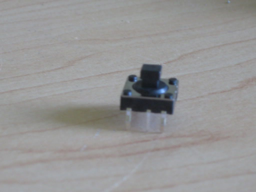
Okay. You have the six pin package. It looks like Number 1.
The pins are labelled 1 through 6 on the diagram in the "Style" section beside their picture. The directions A through D are also listed.
Underneath this chart are two pinouts. For the four-directional tact, you only use pins 1 through 5.
Pin four is a common pin, and is shared between all of the connections. When you tilt the tact in the up (or A) direction, pins 1 and 4 will be connected. When you tilt it in the C direction (down), pins 3 and 4 will be connected.
Edit nevermind.
The diagram is only displaying 5 pins (there are 6)
Also how do i know which is number 1?
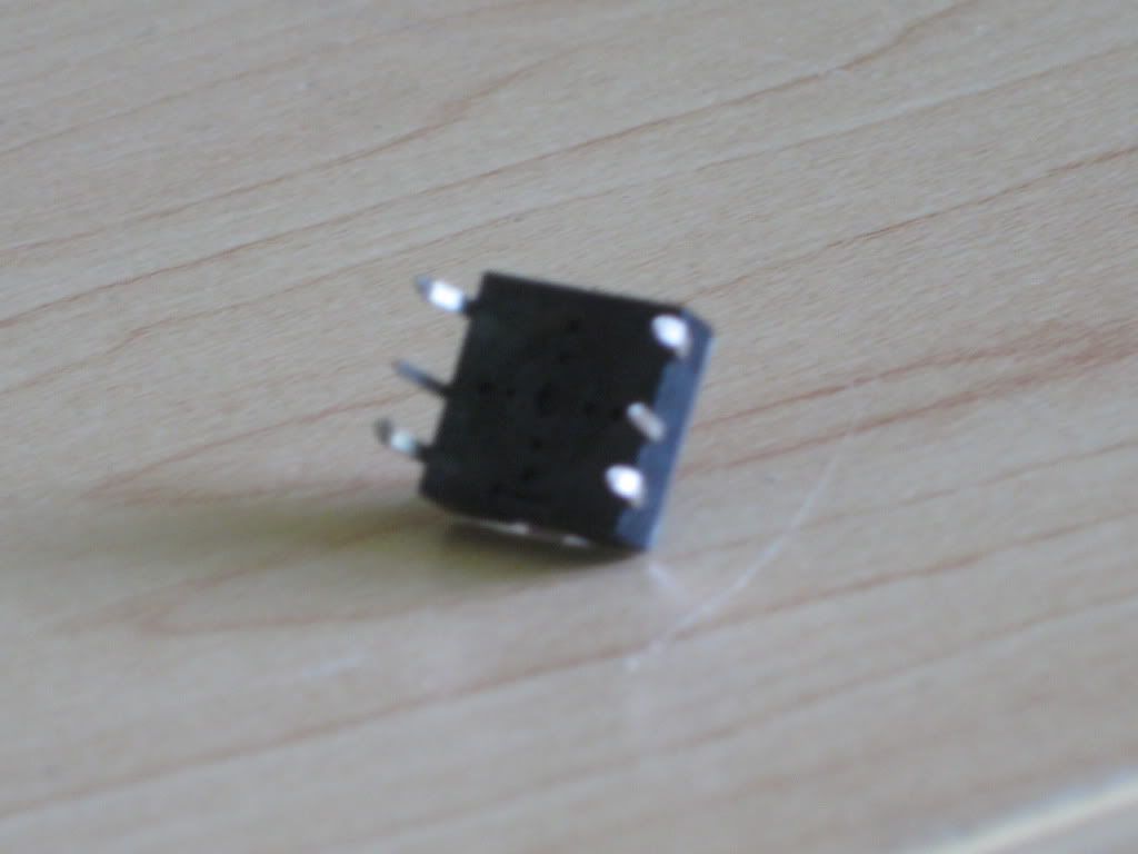
Edit 2: If it was up to me, i would guess that the four pins on the outside (which are bent) go to each direction and the two pins in the middle go to ground..
But it's not up to you. 6 pins is a standard package. It's cheaper to make because the machines to make five pins would have to be custom. So they just use the same machine for the tacts with the push-down option as well, and save money.
The sixth pin isn't used on your model. Don't worry about it.
Look for any marking that distinguish one side from the other. If none exist, just stick a multimeter to two pins (like 1 and 4), move the tact up, and check for continuity. If there is none, rotate it 180 degrees and you got it right.
Kurt_ wrote:Look for any marking that distinguish one side from the other. If none exist, just stick a multimeter to two pins (like 1 and 4), move the tact up, and check for continuity. If there is none, rotate it 180 degrees and you got it right.
That's exactly what I did when I used one. I'd provide a pinout that I made, but it has long since disappeared. If you do not own a multimeter, GO GET ONE! You will be able to answer so many of your own questions if you get one and learn how to use it to problem-solve and troubleshoot.
Also, this is going to the Technical Q&A section where it belongs.
dragonhead wrote:sweet. ive spent a third of my life on benheck!